Gradient Controller Tutorial
1Department of Radiology, Case Western Reserve University, United States
Synopsis
Gradient Power Amplifiers (GPAs) are one of the fundamental subsystems in an MRI scanner. In clinical systems, GPAs output thousands of volts and hundreds of amps with great precision and accuracy. Therefore developing a GPA is a daunting, costly, and possibly hazardous task for engineers not familiar with high power systems and control. This educational lecture will review the design and construction of a prototype 2kVA GPA in order to introduce engineers to advanced topics while keeping costs and risks low. The prototype design is open source and the cost of components is under USD $400.
Introduction
!! All design documents for the GPA prototype may be found at https://github.com/mtwieg/Maker-Gradient-Amplifier !!
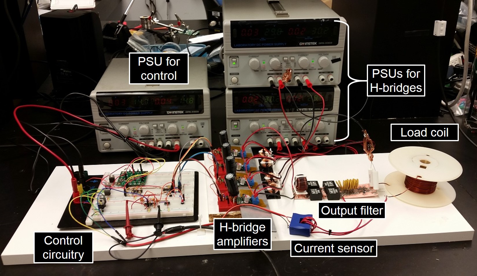
Gradient Power Amplifiers (GPAs) are one of the fundamental subsystems in an MRI scanner. In clinical systems, GPAs output thousands of volts and hundreds of amps with great precision and accuracy. Therefore developing a GPA is a daunting, costly, and possibly hazardous task for engineers not familiar with high power systems and control. This educational lecture will review the design and construction of a prototype 2kVA GPA in order to introduce engineers to advanced topics while keeping costs and risks low. The prototype design is open source and the cost of components is under USD $400. Figure 1 shows a block diagram of the GPA, and figure 2 shows a photo of the assembled prototype.
During the course of the lecture, participants will:
1. Review the structure and operation of modern GPAs
- Pulse width modulation (PWM)
- Benefits of interleaved PWM
- The cascaded H-bridge
- Output filters1
- Current sensors
2. Be introduced to various considerations when working with high voltage systems
- Shock hazards
- Isolation
- Measurement instruments for high voltage
3. Learn simple yet robust methods of designing and verifying feedback controllers
- Stability criteria and margins
- Measuring small signal transfer functions of switchmode systems
- The K-factor method of controller design2,3
Prototype GPA
The GPA was designed such that it exposes the engineer to advanced topics while minimizing the costs and risks associated with full-size GPAs. The criteria of the GPA design was as follows:
1. Shares basic structure with modern GPA designs
- Four cascaded H-bridges each with switching frequency of 50kHz
- Interleaved PWM for an effective switching frequency of 200kHz
- Peak output up to 120V/20A
- Closed loop control bandwidth of 20kHz
2. Low cost components and construction
- Nearly all circuitry assembled on solderless breadboards
- No custom PCB fabrication required
- All
components are available off the shelf
- Uses pre-built H-bridge modules for high performance at low cost
- Entirely analog implementation, no programming required!
- Total estimated cost of components is USD $400
3. Safety
- The combined output voltage is limited to 120V
- Anything over 50V is a potential shock hazard!
- Shock hazards are easily avoided by observing proper guidelines
4. Scalable
- The controller can be expanded by adding more interleaved phases. The LTC6909 can provide up to 14 interleaved clocks (see datasheet)
- The interface between the controller and power stages allows for swapping in higher power H-bridges
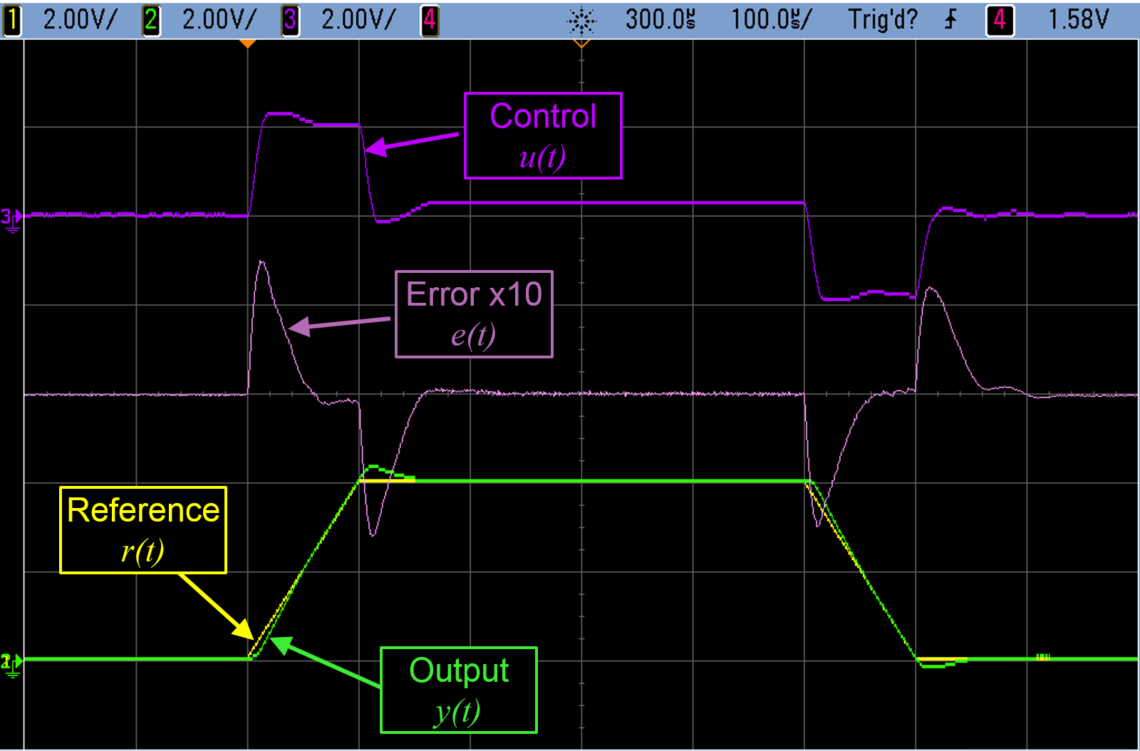
Figure 3 shows operating waveforms of from the GPA prototype. The reference input is a trapezoidal pulse with ramp times of 100μs and a plateau time of 400μs. The pulse amplitude is 16A. The error signal is well damped, and reaches steady state within 50μs.
Open source design
All design documents for the GPA can be downloaded at the repository link found at the top and bottom of the abstract. This includes:
1. Full schematic of the prototype assembly
2. LTspice simulation of a linear time-invariant small signal model of the prototype
- Can be used to simulate transfer function of any part of the controller
- Automatically calculates controller component values based on K-factor method inputs
3. LTspice simulation file for switching behavior of the GPA prototype
- Useful for observing the importance of isolation capacitance and common mode chokes4
- Observe output ripple
- Helps estimate power efficiency
4. Bill of materials
Conclusion
To conclude the lecture, we will discuss various potential improvements in the GPA design, including reduced ripple1, distortion5, noise, and drift6,7. The output voltage or current of the GPA may also be scaled somewhat by adding more H-bridges in series, or implementing the H-bridges with more powerful components. However as power continues to scale, the benchtop PSUs for the H-bridges will become the primary limiting factor. In practice, a more specialized PSU with multiple isolated outputs will be required8–10.
!! All design documents for the GPA prototype may be found at https://github.com/mtwieg/Maker-Gradient-Amplifier !!
Acknowledgements
No acknowledgement found.References
1. Sabate J et al. Ripple cancellation filter for magnetic resonance imaging gradient amplifiers. APEC 2004.
2. Venable H D. The K factor. A new mathematical tool for stability analysis and synthesis (1983).
3. Venable H D. Venable Technical Paper #3, Optimum Feedback Amplifier Design For Control Systems (2017).
4. Lai R et al. Analysis and suppression of a common mode resonance in the cascaded H-bridge multilevel inverter. ECCE 2010.
5. Sabate J et al. Dead-time compensation for a high-fidelity voltage fed inverter. PESC 2008.
6. LEM. Current Transducer IT 700-S ULTRASTAB. Available at: www.lem.com/docs/products/it_700-s_ultrastab.pdf
7. Prodrive Technologies. XPCS-1200 extreme precision current sensor. Available at: www.prodrive-technologies.com/products/xpcs-1200-extreme-precision-current-sensor/.
8. Sabate J et al. Resonant power supply for magnetic resonance imaging gradient drivers. PESC 2003.
9. Zhu P et al. Multi-output power supply with series voltage compensation capability for Magnetic Resonance Imaging system. IPEMC 2009.
10. Sabate J. et al. Magnetic Resonance Imaging Power: High-Performance MVA Gradient Drivers. JESTPE 2016.
Figures