Magnet-Building Tutorial
1Martinos Center for Biomedical Imaging, United States
Synopsis
Compact permanent magnet assemblies are useful for many NMR and MRI applications in both education and research. In this talk, we review practical considerations for the design, assembly, and characterization of compact permanent magnets in a typical lab setting. We will show all the steps for simulating, optimizing and safely building a simple dipole magnet for educational applications. We then review a variety of different permanent magnet designs that are being used in contemporary MR research projects.
Permanent magnet assemblies for education and research: A magnet-building tutorial for makers
The past decade has witnessed renewed interest in compact permanent magnet assemblies for portable diagnostics, food and materials testing, borehole prospecting, magnetic resonance education, and other applications. Permanent magnets offer practical advantages compared to resistive magnets, which have high heat dissipation and require large power supplies, and also compared to superconducting magnets, which require cryogenic hardware, vacuum shields, and special siting. In contrast to resistive and superconducting magnets, it is often feasible to build and use permanent magnet assemblies safely in a typical laboratory setting. This talk will address practical issues involved in designing, building, and characterizing compact permanent magnets. A variety of permanent magnet geometries will then be reviewed – including dipole magnets, single-sided and “inside out” magnets, and Halbach arrays – and the advantages and drawbacks of each design will be considered.
Magnet-building demonstration
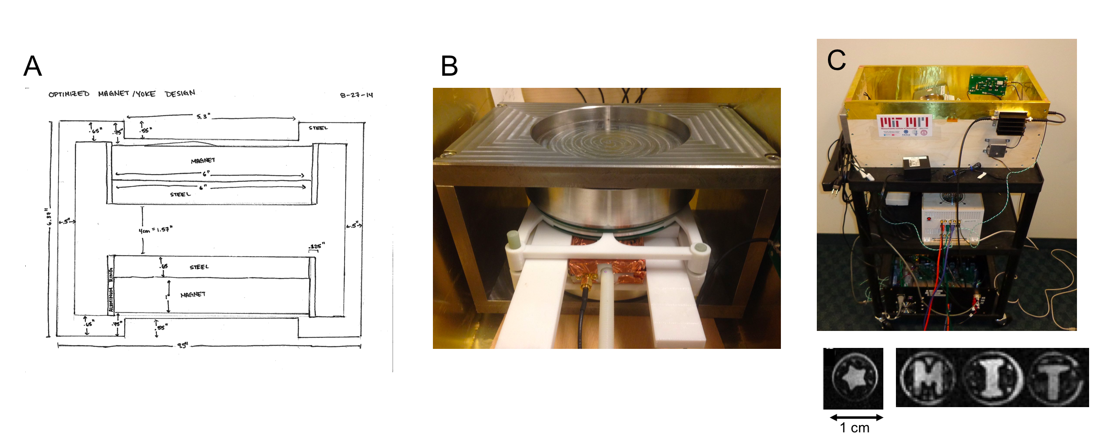
As a practical demonstration, we show the steps for building a simple tabletop 0.36 Tesla dipole magnet using readily-available Neodymium-iron-boron magnetic material (Figure 1a). The magnet is intended for classroom magnetic resonance experiments on 1 cubic centimeter samples. COMSOL simulation software is used to optimize the physical dimensions of the yoke and pole pieces (1018 low-carbon steel) to achieve a target field strength and field homogeneity over the sample volume. A procedure for magnet assembly is then shown. Jigs are used to lower magnetic material onto the yoke in a controlled manner. An aluminum guide ring aligns the permanent magnets to a notch in the yoke, helping ensure symmetry for maximizing field homogeneity. The two magnet halves are then brought together using a different jig. The center frequency of the magnet assembly is then measured using a Hall effect field probe. The linewidth is estimated by moving the probe around the imaging volume and repeating the measurements. The completed magnet is then integrated into an open-source educational MRI scanner [1,2] capable of 3D imaging (Figure 1b). The homogeneity over the 1 cc sample is approximately 50 ppm before applying linear shims and 20 ppm after shimming. Approximate cost: $1K for magnets and $2K USD for yoke and pole pieces.Other permanent magnet examples
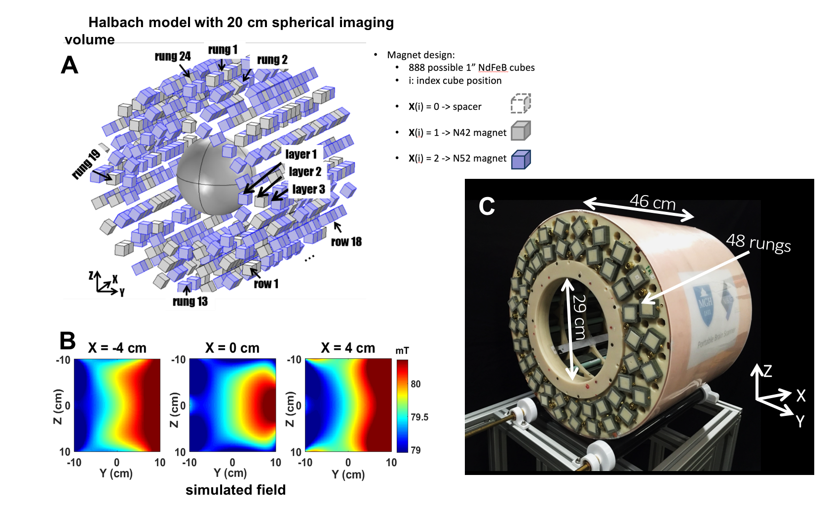
Taking the dipole magnet as a point of departure, we will then discuss a few permanent magnet designs being used in contemporary magnetic resonance research. For the first research example, shown in Figure 2, a genetic algorithm is used along with COMSOL simulations to optimize the design of Halbach magnet array for use as a portable brain scanner. The goal is to create a field with maximum B0 field strength and an “always-on” spatial encoding magnet field that varies approximately linearly across the field-of-view. During optimization, the algorithm chooses the strength of the magnetic material to use at each position in the Halbach rungs, subject to a 100 kg maximum weight constraint for the magnets and a target average field strength of 80 mT (Figure 2a) [3]. Approx. cost: $5K for magnets (plus cost of rungs and alignment rings).
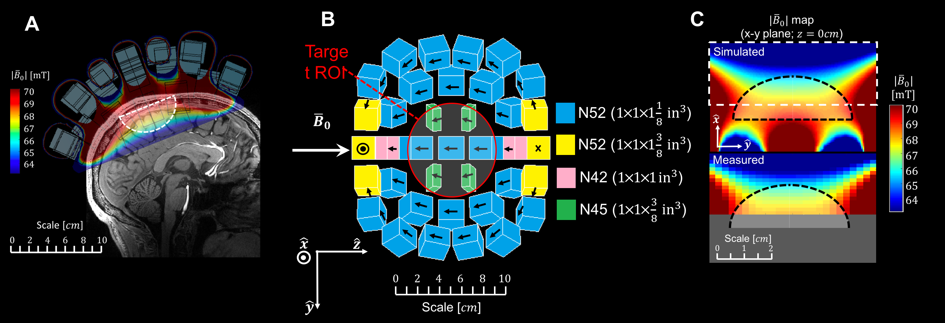
The second research example, shown in Figure 3, is a 6 kg single-sided helmet-shaped magnet for brain imaging with a sensitive region that extends 3 cm into the brain [4]. The system is intended for brain depth profiling and imaging using a low-cost, portable diagnostic tool. In this design, a Halbach sphere [5] is discretized into a design that can be built from relatively inexpensive block magnets mounted onto a 3D-printed former with epoxy. The position and orientation of the block magnets was then optimized using a genetic algorithm to approximate the desired spatial field profile and average field strength (> 50 mT). Approx. cost: $450 USD for magnets.
Conclusion
In summary, we have reviewed practical design and safety considerations for simulating and building permanent magnet assemblies.Acknowledgements
We thank Lawrence Knowles of PRC Machine for help with fabricating yokes and pole piece for magnet assemblies shown in this talk.References
1. Cooley CZ, Stockmann JP, LaPierre C, Witzel T, Jia F, Zaitsev M, Stang P, Scott G, Wald LL, 2014. Implementation of low-cost, instructional tabletop MRI scanners. Proc Intl Soc Mag Reson Med 22, p. 4819.
2. https://tabletop.martinos.org/index.php/Main_Page
3. Cooley CZ, Haskell MW, Cauley SF, Sappo C, Lapierre CD, Ha CG, Stockmann JP, Wald LL. Design of Sparse Halbach Magnet Arrays for Portable MRI Using a Genetic Algorithm. IEEE Trans Magn. 54;1:2017.
4. McDaniel P, Cooley C, Stockmann JP, Wald LL, 2018. A 6.3kg Single-Sided Magnet for 3D, Point-of-Care Brain Imaging. In: Int. Soc. Magn. Res. Med. 26th Annual Meeting, 2018.
5. Blümler P, Casanova F (2016). Hardware Developments: Halbach Magnet Arrays. New Developments in NMR No. 5 Mobile NMR and MRI: Developments and Applications (pp. 133-157). London, England: The Royal Society of Chemistry.
Figures