Waveform Generator Tutorial: RF Vector Modulator
1National Institutes of Health, United States
Synopsis
This presentation will be focused on methods for the design and implementation of a pTx controller to be connected to an available MR console.
Target Audience
Those interested in the design of in-house systems for pTx applicationsObjective
This presentation will cover
- RF pTx pulse specifications
- RF vector modulation principle
- Selection of available integrated circuits (ICs)
- Modulation control
- Applications
Introduction
In a multi-channel or parallel transmission (pTx) setup the transmit (B1) field spatiotemporal profile can be fully controlled by independent control of the waveform, amplitude and phase of the transmit pulses in the individual channels. This makes pTx a very promising approach: i-at high and ultra-high field, for shimming the B1 field to compensate dielectric artifacts due to the short excitation wavelength, and ii-at lower fields, for minimization of the RF electrical field (E1) in metallic implants to improve safety. Thus, multi-channel transmit arrays are becoming more common in body and brain imaging applications. A true pTx operation requires independent control of the current/voltage per channel. In the past, most commercial systems lacked such pTx control and in-house controllers based on vector modulation were built in research sites [1-3]. Today many research sites have commercial MRI systems with up to eight independent TX channels. However, expansion to a higher density transmitter still requires the design and implementation of additional TX control hardware. In addition, a version of such hardware might be necessary for controlling non-conventional amplifiers [4,5]. In this presentation I will demonstrate how to build a pTx controller from low-cost commercial off-the-shelf ICs that meet the specifications for most MRI transmit applications. Following is a brief review of the vector modulation operation principle and control.RF Vector Modulation
In most MRI applications, we work with narrowband modulated signals. In a multi-channel transmitter, the RF voltage (or current) pulse in channel i is given by:
$$p_i (t)=A_i s_i (t)cos[ω_c t-ϕ_i(t)]$$ Eq. (1)
Where Ai is the amplitude, si(t) is a normalized modulating envelope or “shape” function and φi(t) is the phase for channel i. By using the cosine trigonometric identity and rearranging terms, the following equation is derived:
$$ p_i (t)=\color{blue} {A_i s_i (t)cos[ϕ_i(t)]}cos(ω_c t)+\color{blue} {A_i s_i (t)sin[ϕ_i(t)]}sin(ω_c t)$$Eq. (2)
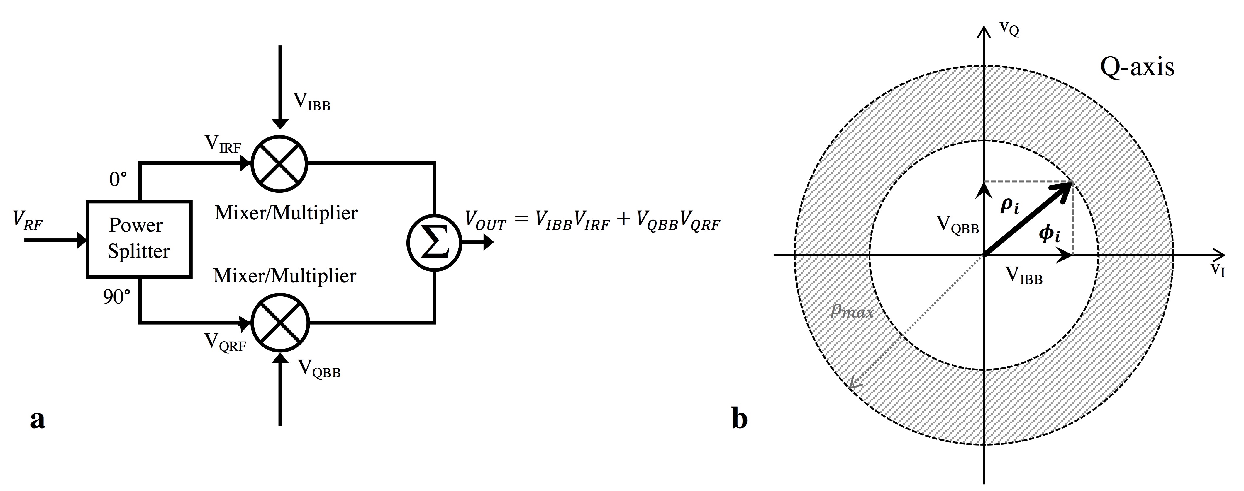
This equation is formed by the sum of two products, the right side is the product between an in-phase baseband (spectrum centered around zero frequency) signal and an in-phase carrier signal while the second term is the product between the quadrature components of same signals. This modulation can be implemented with a quadrature (or I/Q) modulator (or upconverter) [6,7]. A simplified diagram is shown in Figure 1a. The voltage at the output of the modulator, now a bandpass signal (in a higher frequency band), is given by:
$$V_{OUT,i} (t)=\color{blue}{V_{IBB,i}(t)}V_{IRF,i} (t)+\color{blue}{V_{QBB,i} (t)}V_{QRF,i} (t)=p_i (t)$$ Eq. (3)
Where VIBB,i and VQBB,i are the in-phase and quadrature baseband control voltages that correspond to the terms highlighted in blue in Eq. (2); VIRF,i and VQRF,i are the in-phase and quadrature components of the carrier signal for channel i. By controlling the VIBB,i and VQBB,i voltages we control the magnitude and rotation of a vector in the I-Q plane as shown in Figure 1b. For a given vector amplitude ρi and phase Φi at a given time t, the baseband control voltages are given by:
$$V_{IBB,i}=ρ_i cos(φ_i)$$Eq. (4)
$$V_{QBB,i}=ρ_i sin(φ_i)$$Eq. (5)
A pTx controller built with vector modulators will have as many vectors as transmit channels, which can be independently rotated with different amplitudes as set by the independently controlled pair of baseband voltages. Note that the RF input of the modulator could also be a modulated carrier (carrier multiplied by si(t) ). In this case the modulation of I/Q inputs will change only the amplitude and phase of the signal. The type of control implemented for these voltages will depend on the desired pTx application, as detailed below.
Modulation Control
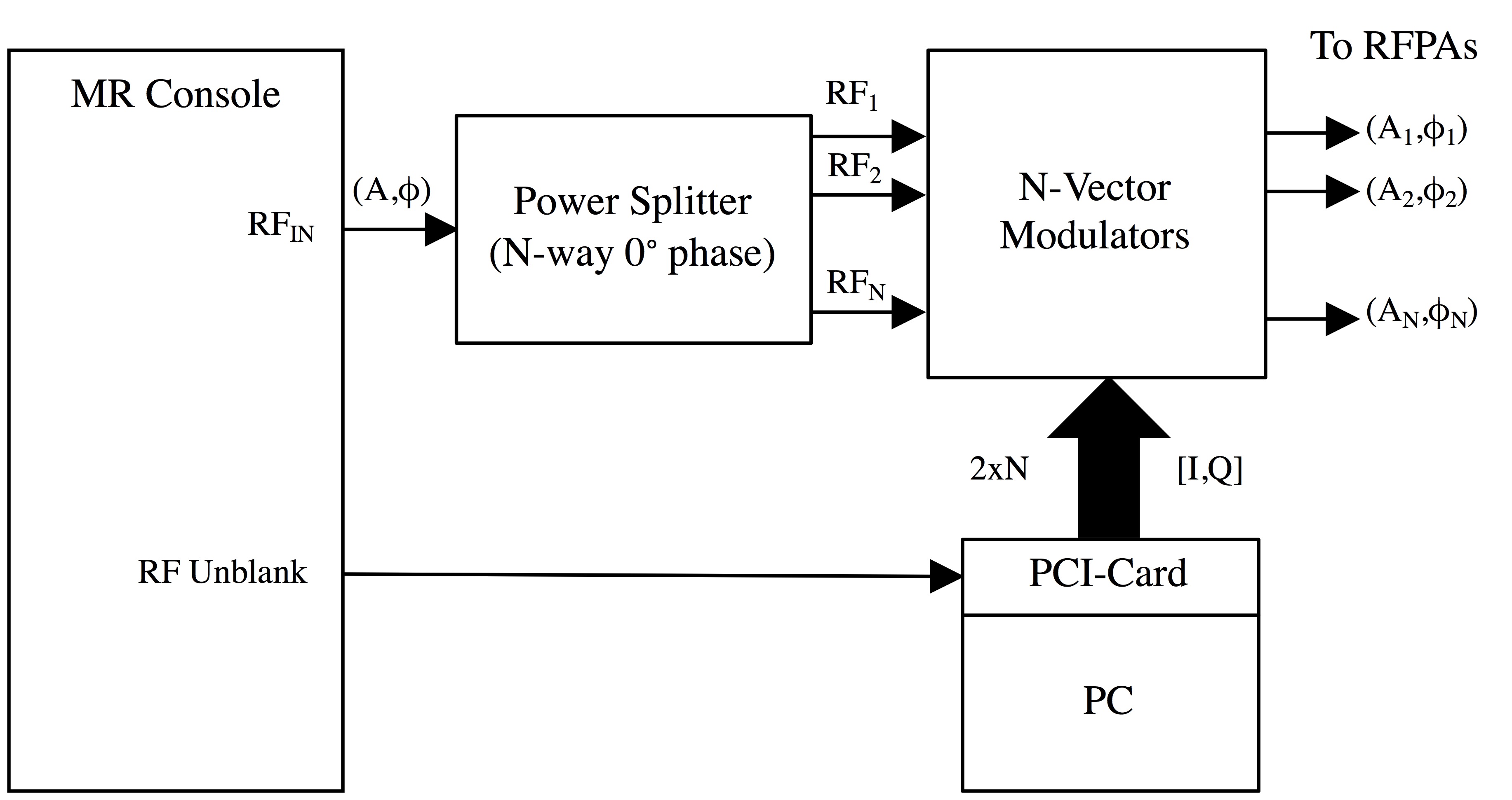
Figure 2 shows a simplified diagram of an implementation of an N-channel pTx interface built with vector modulators to connect to an available console. In this implementation, the baseband voltages are generated by a PC with a peripheral component interconnect (PCI) card that has a sufficient number of analog outputs (2xN DACs) to control the modulators. The RF inputs to the multiple modulators can be the small RF signal (before amplification), available in most MR consoles, through an N-way, 0° phase power splitter. The I/Q outputs of the pTx control can be triggered by the RF unblank available in the MR console. We can perform a “static” control of the modulator baseband I/Q signals, where ρi and φi are constant values across the duration of the RF pulse (e.g. for B1 shimming applications). For the generation of more complex, tailored pTx pulses (e.g. RF spokes), we perform a “dynamic” control of the I/Q signals per channel (with sub-microsecond time resolution) across each RF excitation.Discussion
Today we can find high performance and low-cost I/Q modulator ICs. However, we still need to consider small deviations from the ideal modulator, most of which can be compensated through calibration [6,8]. A mismatch between the in-phase (I) and quadrature (Q) control signals can result in amplitude and phase errors of the transmit signal per channel, while a DC offset in these inputs will generate an unmodulated component of the carrier at the modulator output (RF leakage). In addition, RF feedthrough and feedback interference across the electronics can also generate spurious components at the modulator output. We will review these imperfections, together with RF pulse specifications for MRI, to select the right components to build a low-cost, broadband and modular pTx controller. This controller will be considered as an additional hardware to be connected to any available console. Alternatively, a standalone pTx controller requires the design of the RF synthesizer, for example, using a direct digital synthesizer (DDS) [9,10]. Besides vector modulation, I will present other signal manipulation methods adopted for the design of a pTx interface that can control switch-mode, instead of linear, RF power amplifiers.Acknowledgements
References
- Stang PP, Kerr A, Pauly JM, and Scott GC, “An extensible transmit array system using vector modulation and measurement,” In Proceedings of the 16th Annual Meeting of ISMRM. Toronto, Canada, 2008, Abstract 145.
- Feng K, Hollingsworth N, McDougall M, Wright S. A 64-channel transmitter for investigating parallel transmit MRI. IEEE Trans Biomed Eng 2012;59:2152–2160.
- Hollingsworth N, Moody K, Nielsen J, Noll DC, Grissom WA, Wright S. An Easily Integrated Multichannel Modulator for All Field Strengths. In Proceedings of the 21st Annual Meeting of ISMRM, Salt Lake City, Utah, USA, 2013. Abstract 2744.
- Gudino N, de Zwart JA, Duan Q, Dodd S, van Gelderen P, Duyn J. Broadband Multi-Channel Optical Interface for On-Coil Switch-Mode RF Amplification. In Proceedings of the 22nd Annual Meeting of ISMRM, Milan, Italy, 2014. Abstract 320.
- Gudino N, Duan Q, de Zwart JA, Murphy-Boesch J, Dodd SJ, Merkle H, van Gelderen P, Duyn JH. Optically controlled switch-mode current-source amplifiers for on-coil implementation in high-field parallel transmission. Magn Reson Med 2016;76:340–349.
- Razavi B. RF Microelectronics, 2nd ed. Prentice Hall, 2011. p. 226-249.
- Ruth Umstattd. AN-899 Operating and Evaluating Quadrature Modulators for Personal Communication Systems. Texas Instruments, 1993
- Eamon Nash. AN-1039. Correcting Imperfections in IQ Modulators to Improve RF Signal Fidelity. Analog Devices, 2009
- Jie S, Qin X, Ying L, Gengying L. Home-built magnetic resonance imaging system (0.3 T) with a complete digital spectrometer. Rev Sci Instrum. 2005; 76:105101
- Stang PP, Conolly SM, Santos JM, Pauly JM, Scott GC. IEEE Trans Med Imaging. 2012 Feb;31(2):370-9
Figures