5650
Correction for insufficient spoiling of transverse magnetization in T1 mapping based on the variable flip angle technique1Department of Neurology, Goethe University, Frankfurt/Main, Germany, 2Brain Imaging Center, Goethe University, Frankfurt/Main, Germany, 3Department of Neuroradiology, Goethe University, Frankfurt/Main, Germany
Synopsis
A method is proposed for the correction of insufficient spoiling of transverse magnetization components in gradient echo data that are used for T1 quantification via the variable flip angle (VFA) approach. The method is based on the use of modified flip angles in the VFA algorithm that differ from the actual angles. The advantage is the versatility of the proposed method: from a given set of 21 values P(k,l), suitable correction parameters can be derived for any VFA protocol. In vitro and in vivo experiments show that this novel correction technique considerably increases the accuracy of measured T1 values.
Introduction
The variable flip angle (VFA) method1 is frequently employed for quantitative T1 mapping, acquiring two or more spoiled gradient-echo (GE) data sets with different flip angles (FA), so T1 can be deduced from contrast differences. The method assumes validity of the Ernst Equation, thus requiring full spoiling of transverse magnetization. For this purpose, radio frequency (RF) spoiling2 is commonly used, incrementing the phase difference between subsequent RF pulses by a value ΔΦ. However, residual transverse magnetization components can alter contrasts, thus giving rise to erroneous T1 values3. Correction techniques employ post-processing3 or strong diffusion weighting gradients4. The current approach proposes the use of modified angles (FA') for T1 quantification, which represent the angles for which the Ernst equation yields the actually measured signal levels.Methods
Correction Method: Modified angles FA' are calculated from FA'=C*FA, where the FA' values represent the angles for which the Ernst Equation yields the actually measured signal intensities:
$$S_{meas}=S_{0}\cdot\sin(FA')\cdot\frac{1-\exp(-TR/T1)}{1-\cos(FA')\cdot\exp(-TR/T1)}$$ (Eq. 1)
Thus, FA' maps can be directly used for T1 calculation via the VFA algorithm. The correction factor C is basically a function of FA, TR, ΔΦ, T1 and T2. However, T2 variations are relatively low in brain tissue. Provided that C is mainly independent of T1, C can be approximated for each ΔΦ-value as a function of FA and TR according to:
$$C=\sum_{k,l=0}^{k+l\leq 5}P(k,l)\cdot FA^{k}\cdot TR^{l}$$ (Eq. 2)
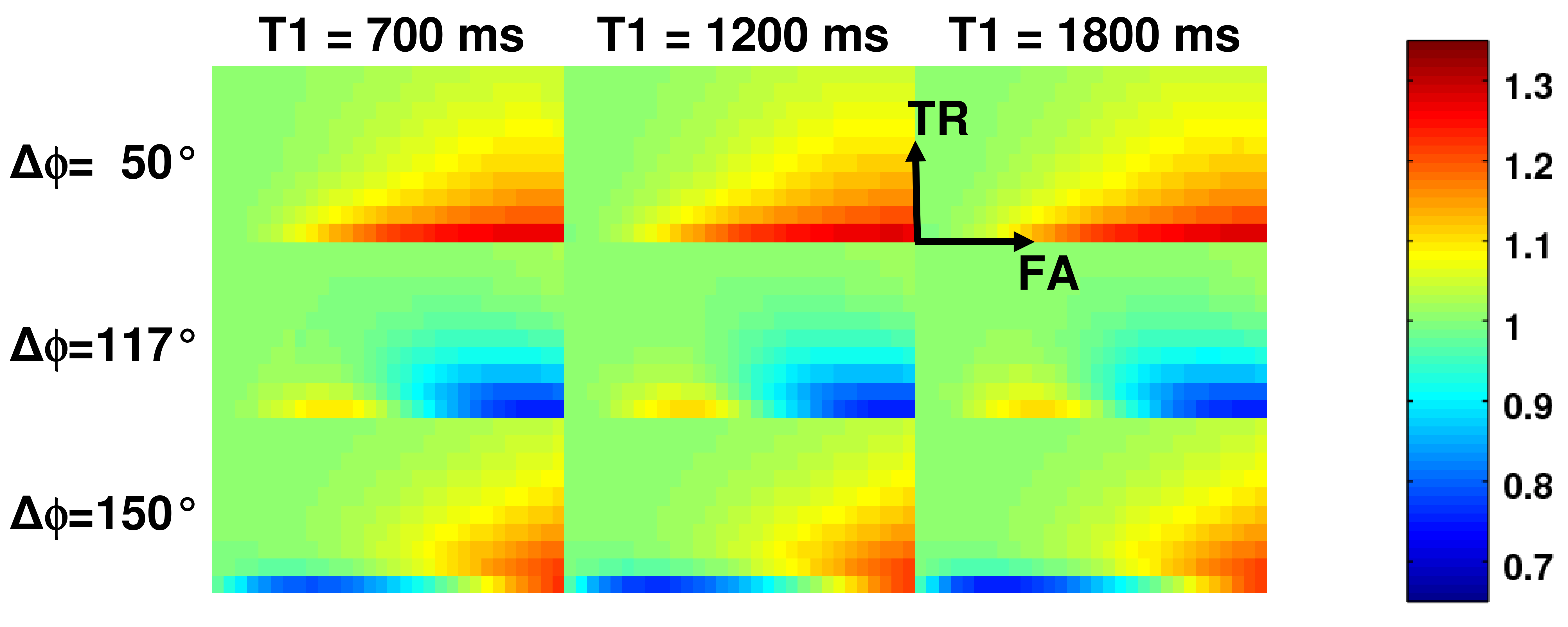
Simulations: For the three most common values of ΔΦ (50°/117°/150°), spoiled GE signal levels were calculated for twelve T1 (700ms-1800ms), a physiological T2 of 85 ms, ten TR (5ms-50ms) and thirty FA values (2°-60°), using a simulation program described in the literature3. In each case, the modified angle FA' and C=FA'/FA were determined. The T1-dependence of C was investigated and C(FA,TR) was fitted according to Eq. 2, yielding the parameters P(k,l).
MR protocols: Experiments were performed on a 3T whole body scanner, using the following protocols:
VFA Protocols: Spoiled GE, FOV=256x224x160mm3, 1mm isotropic resolution, TE=6.7ms. The parameters TR/FA1/FA2/ΔΦ were:
Protocol A: 16.4ms/4°/24°/50°
Protocol B: 16.4ms/4°/32°/50°
Protocol C: 25ms/5°/30°/50°
Protocol D: 16.4ms/4°/24°/117°
Protocol E: 16.4ms/4°/24°/150°
T1-Reference: Inversion Recovery EPI, FOV=192x192 mm2, 3mm in-plane resolution, 6 slices (thickness/gap: 2mm/2mm), TR/TE/FA=30s/26ms/90°, 14 different inversion times (TI).
T2-Mapping: Spin Echo EPI, FOV=256x176 mm2, 2mm in-plane resolution, 11 slices (thickness/gap: 2.5mm/2.5mm), TE=[50, 90, 120] ms.
B1-Mapping: As described previously5, FOV=256x224x160mm3, 4mm isotropic resolution.
Data Analysis: Maps of the actual flip angles FA were calculated by multiplying the nominal FA value with the normalized B1 map. Subsequently, FA' maps were calculated, using the correction factor C as determined for each protocol from Eq. 2 with the parameters P(k,l) as derived from the simulations. The FA' maps were then used in the VFA algorithm for T1 mapping. For comparison, uncorrected maps were also derived, using the original FA maps.
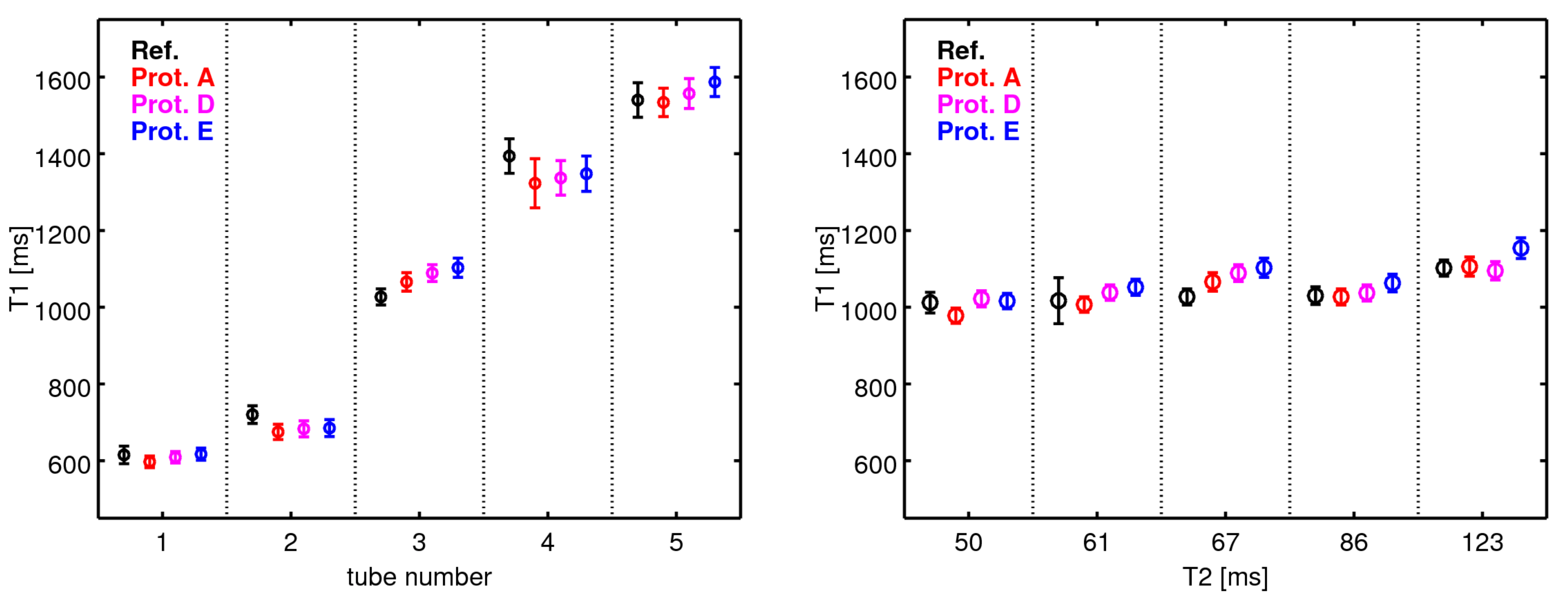
Phantom Experiment: The phantom was a cylindrical container filled with water. Embedded were nine 50 ml tubes, filled with agarose gel, 0.9% NaCl solution and different quantities of 1mmol/l Gadobutrol (2.13 to 11.78 ml). The phantom consisted of two parts:
T1-Phantom: T1 range: 600-1600 ms, T2: ~70 ms
T2-Phantom: T2 range: 50-120 ms, T1: ~1100 ms
In Vivo Experiment: Measurements were performed on five healthy subjects (2 female, age range 25-41 years) who gave written informed consent before participation.
Results
Simulations: Figure 1 shows C(FA,TR) for T1=[700,1200,1800ms] (columns) and ΔΦ=[50°,117°,150°] (rows). Obviously, C(FA,TR) is largely independent of T1.
Phantom Experiment: Figure 2 shows the results for the T1 phantom (left) and the T2 phantom (right). For all tubes, there is a good agreement between reference T1 values and corrected VFA based values (left). Furthermore, the correction procedure yields reliable values for a range of T2 values between 50 and 120 ms (right).
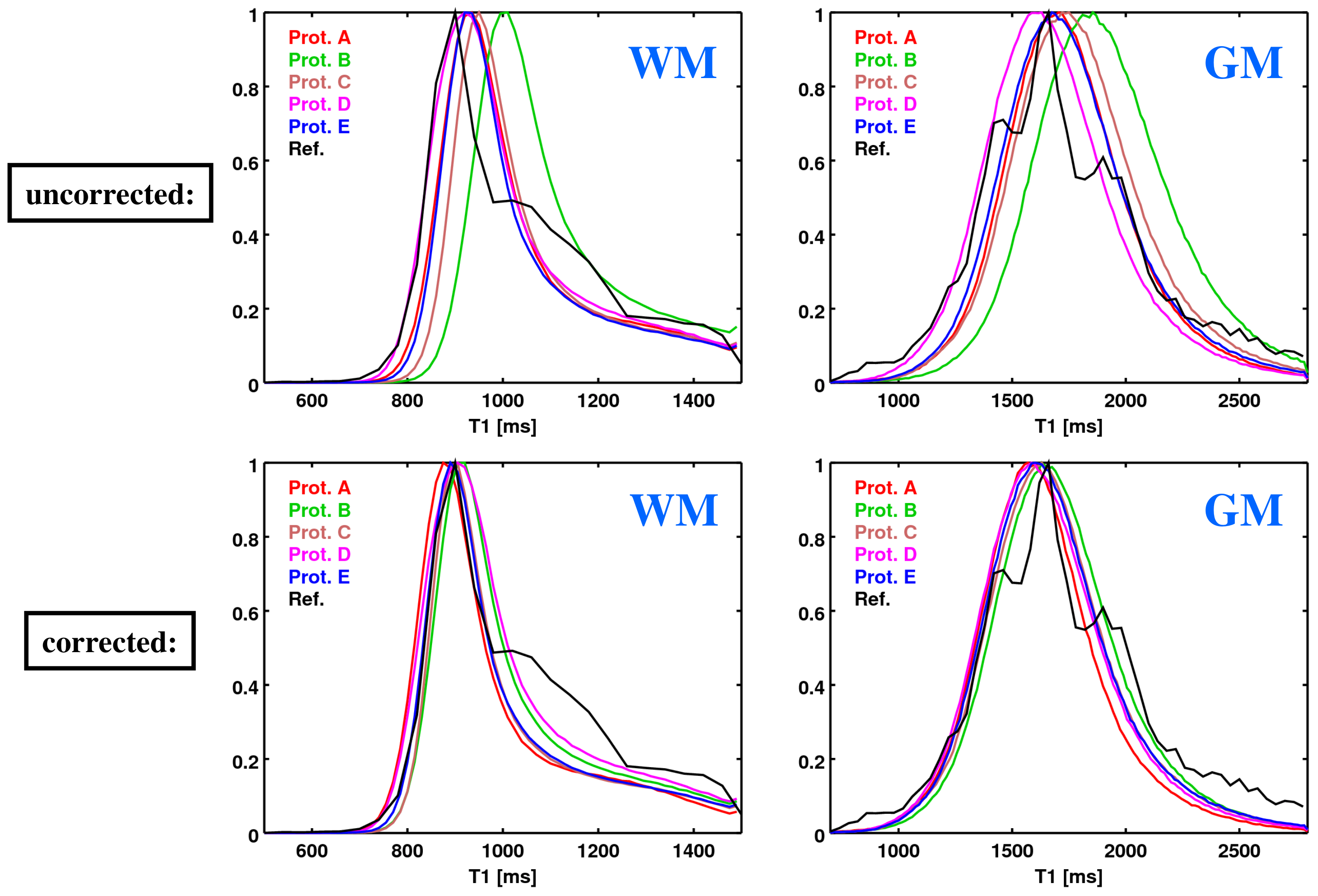
In Vivo Experiment: Figure 3 shows histograms of uncorrected (top) and corrected (bottom) T1 values, both across WM (left) and GM (right). Correction improves considerably the consistency between the VFA-based and reference results.
Discussion
The proposed method allows for correction of insufficient spoiling in GE data, thus enhancing the accuracy of T1 values measured via the VFA method. The advantage is the method's simplicity: for any GE experiment using a given ΔΦ for RF-spoiling, the same set of 21 values P(k,l) can be used to derive a correction factor C(FA,TR) which is mainly independent of T1 and allows to convert real flip angles (FA) into FA' values for which the Ernst equation is valid. The method can be applied to any quantitative GE data analysis using the Ernst equation, such as VFA-based mapping of T1 or proton densities.Acknowledgements
No acknowledgement found.References
1. Wang HZ et al., Optimizing the precision in T1 relaxation estimation using limited flip angles. Magn Reson Med 1987;5:399-416
2. Zur Y et al., Spoiling of transverse magnetization in steady-state sequences. Magn Reson Med 1991;21:251-263.
3. Preibisch C and Deichmann R, Influence of RF spoiling on the stability and accuracy of T1 mapping based on spoiled FLASH with varying flip angles. Magn Reson Med 2009;61:125-135
4. Yarnykh VL, Optimal radiofrequency and gradient spoiling for improved accuracy of T1 and B1 measurements using fast steady-state techniques. Magn Reson Med 2010;63:1610-1626
5. Volz S et al., A fast B1-mapping method for the correction and normalization of magnetization transfer ratio maps at 3 T. Neuroimage 2010;49:3015-3026
Figures