5231
Stick, ball, and plane phantoms for validation of diffusion MRI1Random Walk Imaging, Lund, Sweden, 2Lund University, Lund, Sweden, 3CR Competence, Lund, Sweden
Synopsis
When using quantitative measurements, sensitive to subtle errors, access to a stable reference object is crucial to validate parameter accuracy, and system fluctuations. Here, we propose three complementary phantoms providing ideal systems for validation of metrics of diffusivity, microscopic anisotropy, and compartment orientation. We have used liquid crystals to design phantoms exhibiting local diffusion tensors with normalized anisotropy (DΔ) equal to the theoretical values of +1 (sticks), 0 (balls), as well as –½ (planes). We also confirm that our proposed phantoms have the desired properties with regards to voxel-average diffusion tensors and microscopic diffusion tensors.
Introduction
Diffusion MRI allow distribution estimation of tissue compartments even on the microscopic scale, enabling tissue feature quantification. For example, microscopic fractional anisotropy (μFA) (1) describing compartment shape, could be interpreted as shape of cells in tissue (2-5), with the potential to assist tumor grading and treatment response (6). Quantitative measurements, sensitive to subtle errors, require access to a stable reference object to validate parameter accuracy, and system fluctuations. To accurately determine the microstructure in tissue it is crucial to reassure that the chosen methods have the capability to separate the shape (sticks, balls and planes) of the microscopic diffusion tensors. Here, we propose three complementary liquid crystal phantoms, providing ideal systems for the validation of metrics of diffusivity, microscopic anisotropy, and compartment orientation.
Methods
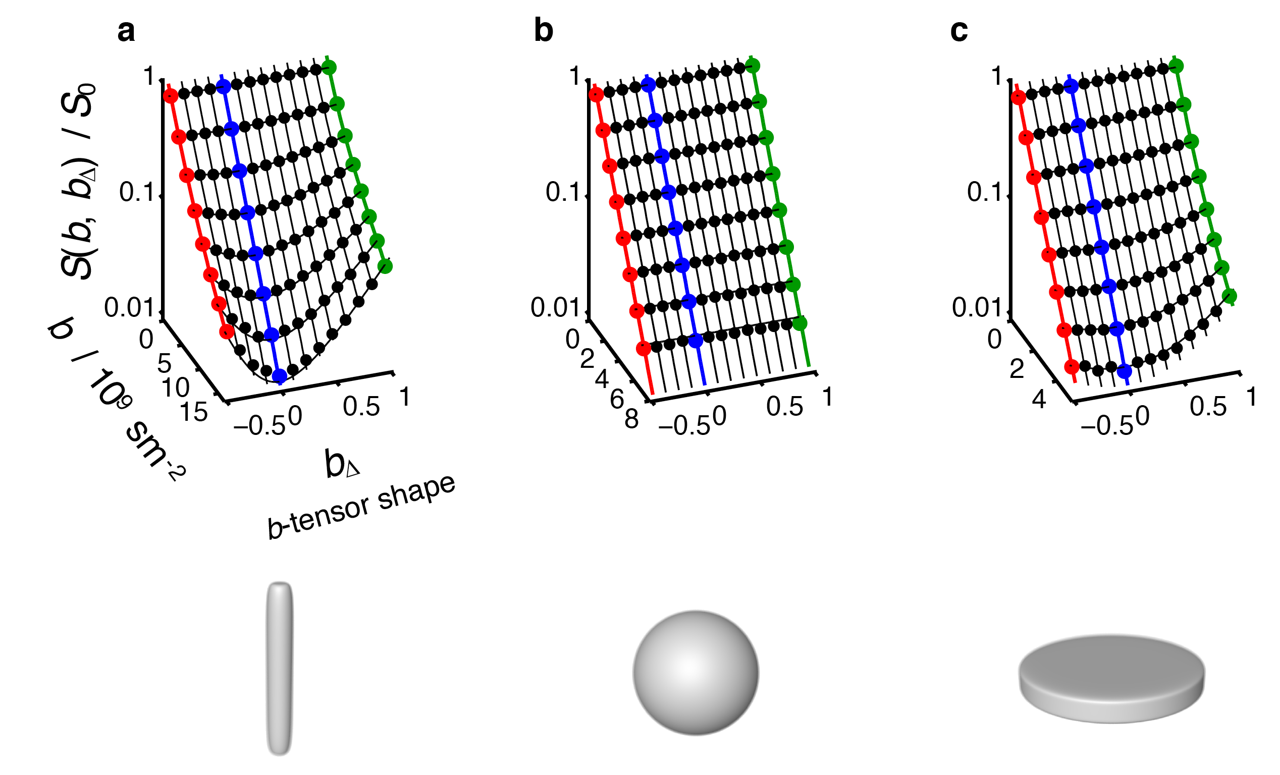
Our aim was to use liquid crystals for the design of phantoms exhibiting local diffusion tensors with normalized anisotropy (DΔ) equal to the theoretical minimum and maximum values of –½ (planes) and +1 (cylinders), as well as 0 (spheres). We define DΔ as $$$\frac{1}{3D_{iso}}(D_{par}-D_{perp})$$$, where isotropic diffusivity is given by $$$D_{iso} = (D_{par}+2D_{perp})/3$$$. In the liquid crystals the water is located in compartments with at least one dimension on the nanometer scale. A schematic overview of phantom microstructures is shown in Fig. 1. The liquid crystals are spontaneously formed by mixing surfactants, oil and water, and by tuning the concentrations, we obtained microstructures exhibiting the desired properties. We selected the names of the phantoms with inspiration from the shape of the corresponding diffusion tensors. The Stick Phantom was made of a liquid crystal with a microstructure corresponding to hexagonally packed water channels in a continuous matrix of oil and water (7). The Ball Phantom was made of a liquid crystal with a bicontinuous cubic structure (8), corresponding to an isotropically interconnected pore space. To obtain a Plane Phantom we used a lamellar liquid crystal (9), with stacked planes of the surfactant separated by water layers.
Diffusion MRI experiments were performed on a 11.7 T Bruker microimaging system using a single-shot RARE pulse sequence with modulated gradient waveforms giving diffusion encoding as a function of the magnitude, shape, and orientation of the b-tensor (8,10,11). After conventional image reconstruction, the data for each voxel was processed with standard DTI analysis, giving the voxel-average diffusion tensor $$$\langle$$$D$$$\rangle$$$, as well as Pake analysis (8,11,12) yielding the microscopic diffusion tensor D which is unaffected by orientation dispersion. Pulse sequence and Matlab code for data processing is available at https://github.com/markus-nilsson/md-dmri. A schematic geometry of the experiment is shown in Fig. 2.
Results
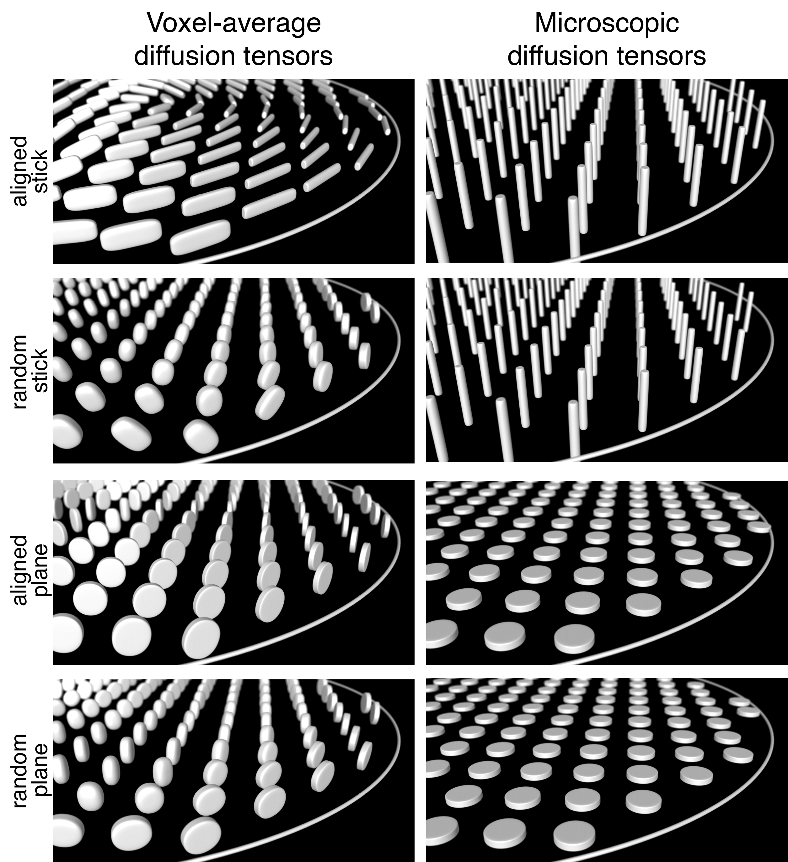
We have confirmed that the spontaneously formed liquid crystals exhibit the expected microstructures. In Fig. 3 the signal vs. b and bΔ (In analogy with the description of the diffusion tensor, the b-tensor can be expressed in its principal axis system where b is the trace of the b-tensor and the b-tensor anisotropy is equal to bΔ ) is displayed for the Stick, Ball-, and Plane Phantoms, showing that microscopic diffusion tensors result in distinguishable signal characteristics. Fig. 4 shows the voxel-averaged diffusion tensors for the oriented- and randomly distributed crystal domains in the Plane- and Stick Phantoms. These results reveal that the obtained information on pore shape and orientation is entangled. In Fig. 4 the corresponding results are shown for the microscopic diffusion tensors, where the information of pore shape is well captured.Discussion
The proposed phantoms have the desired microstructural properties for validation of any method aspiring to determine the microscopic anisotropy in for example tissue. The phantoms can also be scaled up to the volumes required for use in a clinical scanner (12). The experimental results confirm that our Pake analysis (8,11,12) of b-tensor encoded data gives correct information about the microscopic pore shape under conditions where conventional DTI analysis completely fails because of orientation dispersion.Conclusions
We suggest our liquid crystal phantoms as the “gold standard” for parameters capturing microscopic anisotropy in any of its incarnations (e.g. DΔ (11), µFA (1), FE (4), Cµ (14), IMA (3), fneurites (15), fsticks (16), E(φ) (17)). It is crystal clear that whenever a protocol has been modified or implemented on a new MR scanner, these phantoms should be used for validation to confirm that the used methods have the ability to separate sticks, balls and planes and thereby have the capability to fully capture the true microscopic structure of any tissue.Acknowledgements
We thank the Swedish Research Council (VR), the Swedish Foundation for Strategic Research (SSF) and Random Walk Imaging (RWI) for funding.References
1. Lasič S, Szczepankiewicz F, Eriksson S, Nilsson M, Topgaard D. Microanisotropy imaging: quantification of microscopic diffusion anisotropy and orientational order parameter by diffusion MRI with magic-angle spinning of the q-vector. Front Physics 2014;2:11.
2. Cory DG, Garroway AN, Miller JB. Applications of spin transport as a probe of local geometry. Polymer Prepr 1990;31:149-150.
3. Lawrenz M, Finsterbusch J. Double-wave-vector diffusion-weighted imaging reveals microscopic diffusion anisotropy in the living human brain. Magn Reson Med 2013;69:1072-1082.
4. Jespersen SN, Lundell H, Sønderby CK, Dyrby TB. Orientationally invariant metrics of apparent compartment eccentricity from double pulsed field gradient diffusion experiments. NMR Biomed 2013;26:1647-1662.
5. Szczepankiewicz F, Lasič S, van Westen D, Sundgren PC, Englund E, Westin C-F, Ståhlberg F, Lätt J, Topgaard D, Nilsson M. Quantification of microscopic diffusion anisotropy disentangles effects of orientation dispersion from microstructure: Applications in healthy volunteers and in brain tumors. Neuroimage 2015;104:241-252.
6. Szczepankiewicz F, van Westen D, Englund E, Westin C-F, Ståhlberg F, Lätt J, Sundgren PC, Nilsson M. The link between diffusion MRI and tumor heterogeneity: Mapping cell eccentricity and density by diffusional variance decomposition (DIVIDE). Neuroimage 2016;142:522-532.
7. Kronberg B, Holmberg K, Lindman B. Surface Chemistry of Surfactants and Polymers: Wiley; 2014.
8. Eriksson S, Lasič S, Nilsson M, Westin C-F, Topgaard D. NMR diffusion encoding with axial symmetry and variable anisotropy: Distinguishing between prolate and oblate microscopic diffusion tensors with unknown orientation distribution. J Chem Phys 2015;142:104201.
9. Sato D, Obara K, Kawabata Y, Iwahashi M, Kato T. Re-entrant lamellar/onion transition with varying temperature under shear flow. Langmuir 2013;29:121-132.
10. Westin C-F, Szczepankiewicz F, Pasternak O, Özarslan E, Topgaard D, Knutsson H, Nilsson M. Measurement tensors in diffusion MRI: Generalizing the concept of diffusion encoding. Med Image Comput Comput Assist Interv 2014;17:209-216.
11. Topgaard D. Multidimensional diffusion MRI. J Magn Reson 2017;275:98-113.
12. Nilsson M, Larsson J, Lundberg D, Szczepankiewicz F, Witzel T, Westin C-F, Bryskhe K, Topgaard D. Liquid crystal phantom for validation of microscopic diffusion anisotropy measurements on clinical MRI systems. Magn Reson Med Accepted.
13. Topgaard D. Director orientations in lyotropic liquid crystals: Diffusion MRI mapping of the Saupe order tensor. Phys Chem Chem Phys 2016;18:8545-8553.
14. Westin C F, Knutsson H, Pasternak O, Szczepankiewicz F, Özarslan E, Van Westen D, Mattisson C, Bogren M, O'Donnell L J, Kubicki M, Topgaard D, Nilsson M. Q-space trajectory imaging for multidimensional diffusion MRI of the human brain. Neuroimage 2016;135:345-62.
15. Zhang H, Schneider T, Wheeler-Kingshott C A, Alexander D C. NODDI: practical in vivo neurite orientation dispersion and density imaging of the human brain. Neuroimage 2012;61:1000-16.
16. Özarslan E, Basser P J. Microscopic anisotropy revealed by NMR double pulsed field gradient experiments with arbitrary timing parameters. J Chem Phys 2008;128:154511.
17. Lampinen B, Szczepankiewicz F, Martensson J, Van Westen D, Sundgren P C, Nilsson M. Neurite density imaging versus imaging of microscopic anisotropy in diffusion MRI: A model comparison using spherical tensor encoding. Neuroimage 2016;147:517-531.
Figures
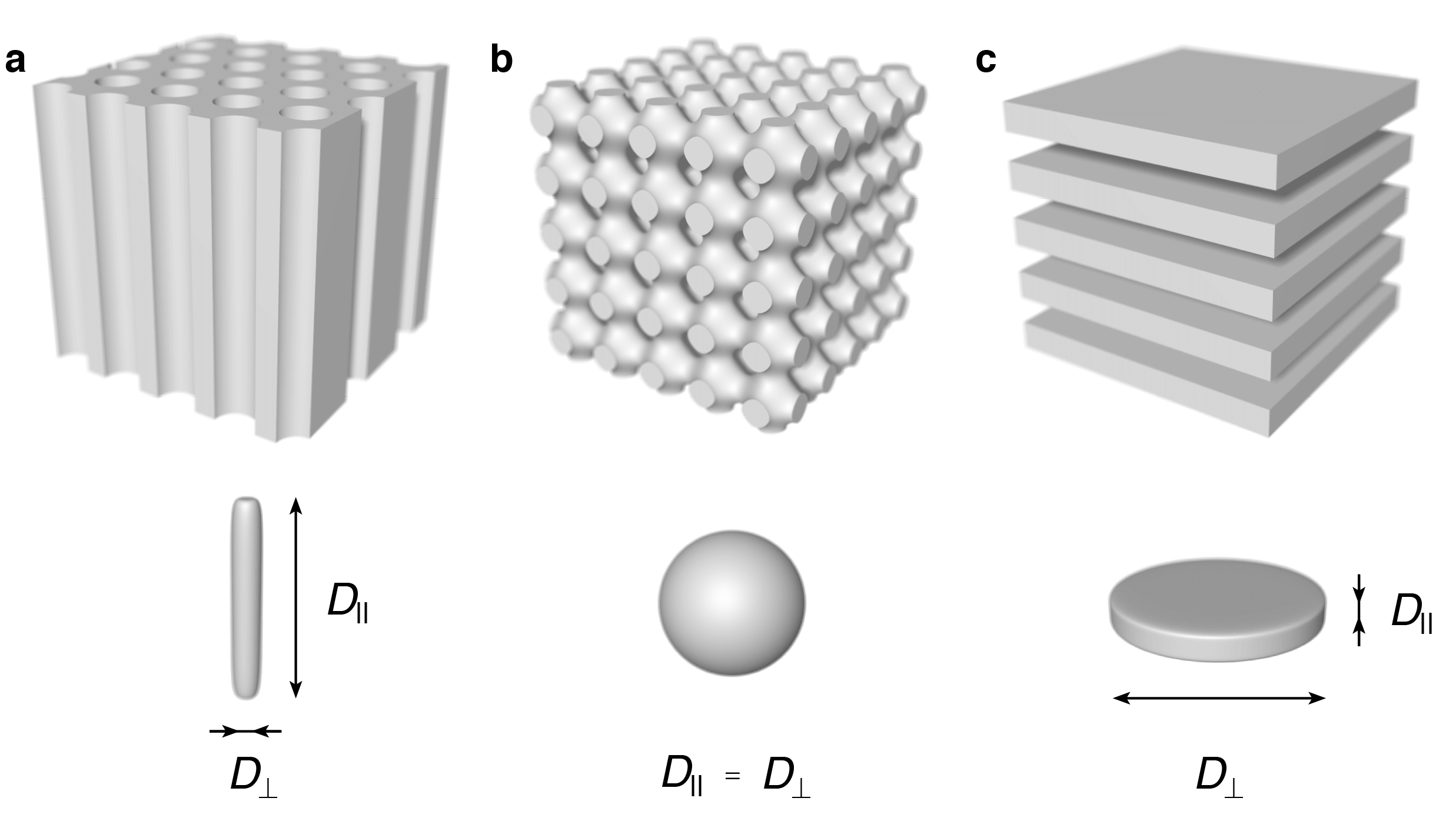
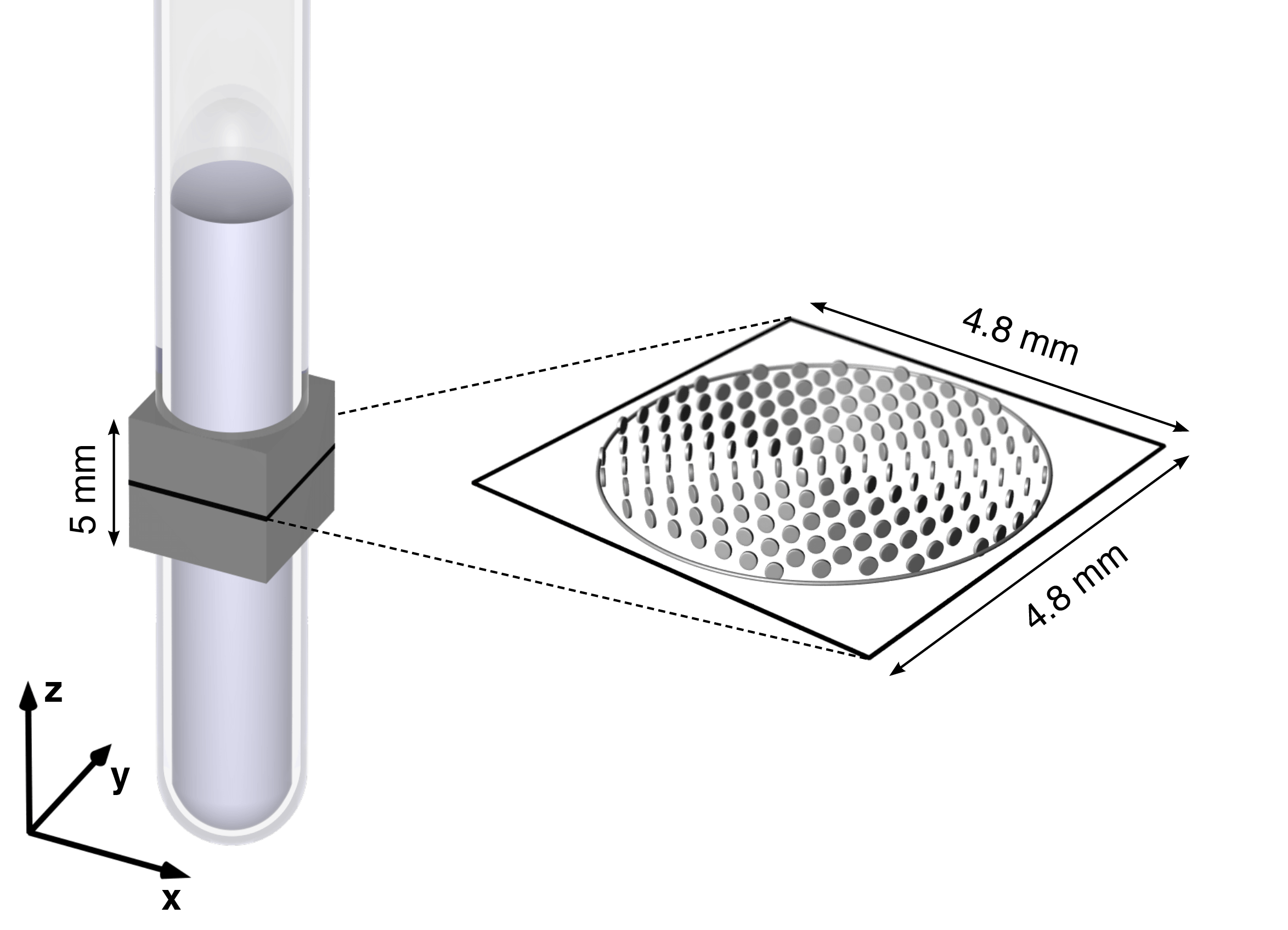
Figure 2. A schematic overview of the MRI experiments. The 0.5 ml liquid crystal is contained by a 5 mm outer diameter NMR tube, with the 5 mm-thick slice excited in these experiments indicated by the gray box. The xyz lab frame is defined by the coils generating the magnetic field gradients. The liquid crystal outer surface, delineated by a gray circle, is imaged within the 4.8 × 4.8 mm field-of-view magnification, denoted by a black square. The voxel-average diffusion tensors $$$\langle$$$D$$$\rangle$$$ for the oriented sample, obtained at 0.3 mm × 0.3 mm resolution in the xy-plane, is represented by the tensor glyphs (13).