5131
OpenForce MR: A Low-Cost Open-Source MR-Compatible Force Sensor1Radiological Physics, University Hospital Basel, Basel, Switzerland, 2Department of Biomedical Engineering, University of Basel, Basel, Switzerland
Synopsis
This work presents an open design for a low-cost (100 USD) MR-compatible force sensor to be used in the context of dynamic muscle MRI/MRS. The sensor is both based on commercial nonmagnetic components and custom manufactured parts. The electronics is realized using Arduino and a prototype software interface is presented. The sensor is calibrated using a commercial dynamometer and shows good linearity in the sensitivity. The setup is proven to function in an MR environment without disturbing the signal acquisition.
Introduction
Measuring physical force during an MR scan is useful in the case of dynamic imaging of the skeletal muscle, for the synchronization of the acquisition with physical measurements as a gold standard or for the quantification of exercise.1 A common solution to the problem is the usage of fiber-optic based force sensors.2–4 These sensors have the advantage of being nonmagnetic and nonconductive, and therefore ideally suited for an MRI environment. The disadvantage of fiber-optic based solutions (comprising both probes and transducer) is that they are available from specialized vendors and their price range is in the tens of thousands of dollars. In this work, we demonstrate the design of an electric force sensor which can be used in an MRI environment entirely built out of off-the-shelf components, with a total cost of around 100 US dollars. This device is demonstrated to function during standard scanning conditions without adverse effects on the acquisition. The design will be made available as open-source on the github public website.Design and Implementation
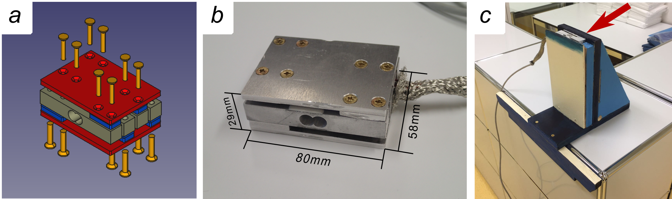
The force sensor is based on four aluminum beam load cells, each capable of sustaining 20kgf (196N), for a total load capacity of 80kgf (784N), mounted on a custom-built aluminum frame. The force is measured by resistive strain sensors connected in a Wheatstone bridge configuration connected in parallel and driven by a single HX7115 amplifier/analog-to-digital converter (ADC) with a temporal resolution of 100ms. The aluminum frame is composed of two plates and eight spacers, cut using a desktop CNC milling machine. The components are assembled using nonmagnetic brass screws. Additional shielding of the connectors is provided by a tinned copper braid (Figure 1). In order to be used inside the scanner, a custom wooden pedal was constructed to measure the force exerted during plantar flexion of the foot (Figure 1c).
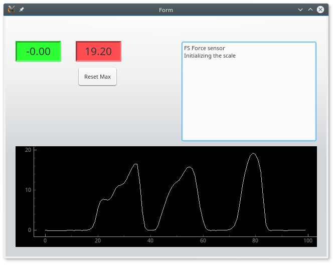
The hardware is connected through a shielded Cat5 ethernet cable to an Arduino6 device mounting an HX711-based shield. The Arduino firmware continuously reads the values of the ADC and converts them into force units (newton, N) according to an experimentally-derived gauge factor. Force values are then sent through serial connection to a personal computer, where a custom Python program reads the values and plots the data (Figure 2).
Experiments
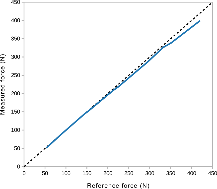
The sensor was calibrated using a commercial dynamometer. Initially, the dynamometer was placed on top of the sensor and a force of 100N was applied. From the reading of the dynamometer, the scaling factor between ADC and force was calculated (through inverse proportionality) and saved in the Arduino firmware.
In order to evaluate the linearity of the response, the procedure was repeated 10 times with force values ranging from 53 to 420N.
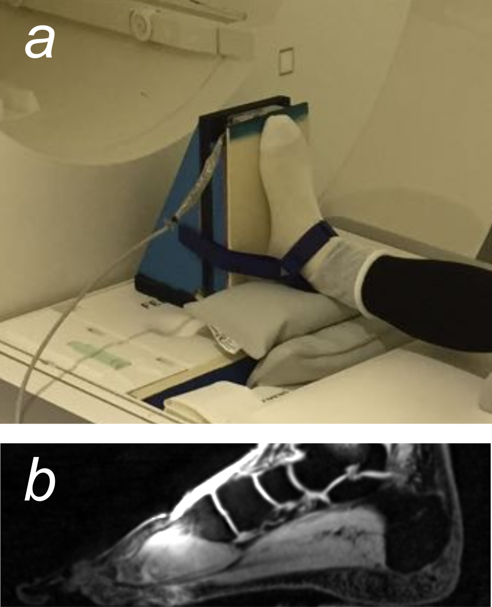
The sensor and the pedal were then placed inside a 3T whole-body MRI scanner (maximum gradient amplitude 80mT/m, maximum slew rate 200mT/m/ms) and a subject was asked to push on the pedal during a conventional velocity-encoded gradient echo acquisition using the gradients at their full power. This sequence was chosen in order to test the robustness of the sensor setup to electromagnetic interference during a realistic usage case. An additional morphological sequence of the foot (3D T1-weighted gradient echo with water excitation, resolution 1x1x1mm3) was obtained to evaluate the presence of RF interference artifacts.
Results
The sensor showed good agreement with the reference dynamometer, with a 5% deviation from linearity at 420N (Figure 3). Inside the scanner, the pedal did not exhibit any attractive force or torque. During scanning, the electronics experienced a reset during the initial frequency adjustment scans; however, during the acquisition of the imaging sequence, the sensor worked within nominal parameters. No RF artifact contamination was present in the acquired images (Figure 4).Discussion
In this work, we demonstrated the design of a low-cost MR compatible force sensor that can be used for the investigation of skeletal muscle function, for example in combination with volitional exercise or electrical muscle stimulation.1,7 The sensor exhibited good MR compatibility, both in sense of functionality during the scan and absence of interferences on the acquired images. The linearity of the sensors is acceptable and could be easily corrected with the software. The temporal resolution of the sensor is currently 100ms, but can be lowered to 10ms according to the specifications of the used ADC.Conclusion
The construction of a low-cost MR compatible force sensor is feasible and, despite being orders of magnitude cheaper than current commercial solutions, it delivers good performance. Both the hardware and the software will be released as open-source so that the whole community can benefit from this design.Acknowledgements
This work was supported by the Swiss National Science Foundation (Nr. 172876).References
1. Malis V, Sinha U, Csapo R, Narici M, Sinha S. Relationship of changes in strain rate indices estimated from velocity-encoded MR imaging to loss of muscle force following disuse atrophy. Magn Reson Med.:n/a-n/a. doi:10.1002/mrm.26759.
2. Chapuis D, Gassert R, Sache L, Burdet E, Bleuler H. Design of a simple MRI/fMRI compatible force/torque sensor. In: 2004 IEEE/RSJ International Conference on Intelligent Robots and Systems (IROS) (IEEE Cat. No.04CH37566). Vol 3. ; 2004:2593-2599 vol.3. doi:10.1109/IROS.2004.1389799.
3. Muscle Activity During MRI with FlexiForce. Tekscan. https://www.tekscan.com/applications/muscle-activity-during-mri-flexiforce. Published December 13, 2013. Accessed August 8, 2017.
4. Johnson M. Measuring Force During Magnetic Resonance Imaging (MRI). Micron Opt. November 2015. http://www.micronoptics.com/measuring-force-during-magnetic-resonance-imaging-mri/. Accessed August 8, 2017.
5. HX711 product page. http://www.aviaic.com/ENProducts.aspx?sort_id=43&FID=1&FID2=43. Accessed November 2, 2017.
6. Arduino. https://www.arduino.cc/. Accessed November 2, 2017.
7. Deligianni X, Pansini M, Garcia M, et al. Synchronous MRI of muscle motion induced by electrical stimulation. Magn Reson Med. 2017;77(2):664-672.
Figures