5091
A Fast and Dedicated First-Order Differencing EPT Reconstruction Method1Circuits and Systems, Delft University of Technology, Delft, Netherlands, 2Centre of Image Sciences, University Medical Centre Utrecht, Utrecht, Netherlands, 3C.J. Gorter Center for High Field MRI, Leiden University Medical Center, Leiden, Netherlands
Synopsis
A new method for reconstructing electrical properties from $$$B_1^+$$$ data based on Maxwell's equations in an E polarized field (found in the midplane of a birdcage coil) is presented. This first-order EPT (foEPT) method uses first order spatial derivatives as opposed to the second order Helmholtz based MR-EPT methods and is thus less susceptible to noise. Furthermore, the method does not rely on any homogeneity assumptions. The method is validated using an in-vivo phantom measurement and compared to an MR-EPT reconstruction. FoEPT conductivity reconstructions show less noise-amplification and less boundary artefacts compared to Helmholtz-based MR-EPT reconstructions.
Introduction
Precise knowledge about the dielectric properties of tissue (conductivity $$$\sigma$$$ and permittivity $$$\varepsilon$$$) is an important prerequisite in many clinical applications. The accurate and efficient reconstruction of these properties from measured $$$B_1^+$$$ data is the main objective of Electrical Properties Tomography (EPT). Over the past decade various EPT methods have been developed, most often based on either the local Helmholtz equation[1-3] or on global integral representations of the RF field.4 Helmholtz-based methods are typically very efficient, but suffer from reconstruction artefacts on tissue interfaces and noise amplification due to the second-order spatial derivatives that act on the $$$B_1^+$$$ data.5 Global methods on the other hand do not suffer from these effects, but are computationally more complex and therefore less efficient.
We propose a new hybrid reconstruction method dubbed first-order EPT (foEPT) which combines the speed of local methods with the accuracy of global methods for tissue interfaces. It requires the E-polarized field structure in the mid-plane of a birdcage coil6 to do so, and uses a first-order spatial derivative as opposed to the second-order Laplacian operator in Helmholtz-based reconstructions and is, therefore, less sensitive to noise. Furthermore, the method can handle inhomogeneous structures and does not rely on any homogeneity assumptions.
Methods
The method works in two steps. First, the induced currents in the sample are determined from the measured $$$B_1^+$$$ field. In particular, for an RF field with an E-polarized field structure,6 the induced current density follows from the $$$B_1^+$$$ data as
$$J_{\mathrm{ind}} = \frac{2}{\mu_0 \mathrm{j}} (\partial_x - \mathrm{j} \partial_y)B_1^+,$$
where $$$\mu_0$$$ is the background permeability, j is the imaginary unit, and $$$\partial_{x/y}$$$ are the spatial derivatives in the $$$x$$$- and $$$y$$$-directions. Second, we relate this current density to the electric field using the global integral representation
$$E + G\{ E\} = E_{\mathrm{inc}} - G\{J_{\mathrm{ind}}\}\qquad\qquad(1)$$
where $$$G\{\cdot\}$$$ is the electric vector potential and $$$E_{\mathrm{inc}}$$$ is the known electric field in an empty coil, which can be simulated using a realistic coil model.
Equation (1) can be solved for the electric field using an iterative solver such as GMRES7 and typically requires only a small number of iterations ($$$\leq$$$10) to reach a satisfactory error level. Having solved Equation (1), the total electric field is known and since the induced electric currents have already been determined, the electrical properties follow as
$$\sigma = \frac{\mathcal{I}(E^* J_{\mathrm{ind}} )}{|E|^2}$$
$$\varepsilon_r = -\frac{\mathcal{R}(E^* J_{\mathrm{ind}} )}{\omega|E|^2}$$
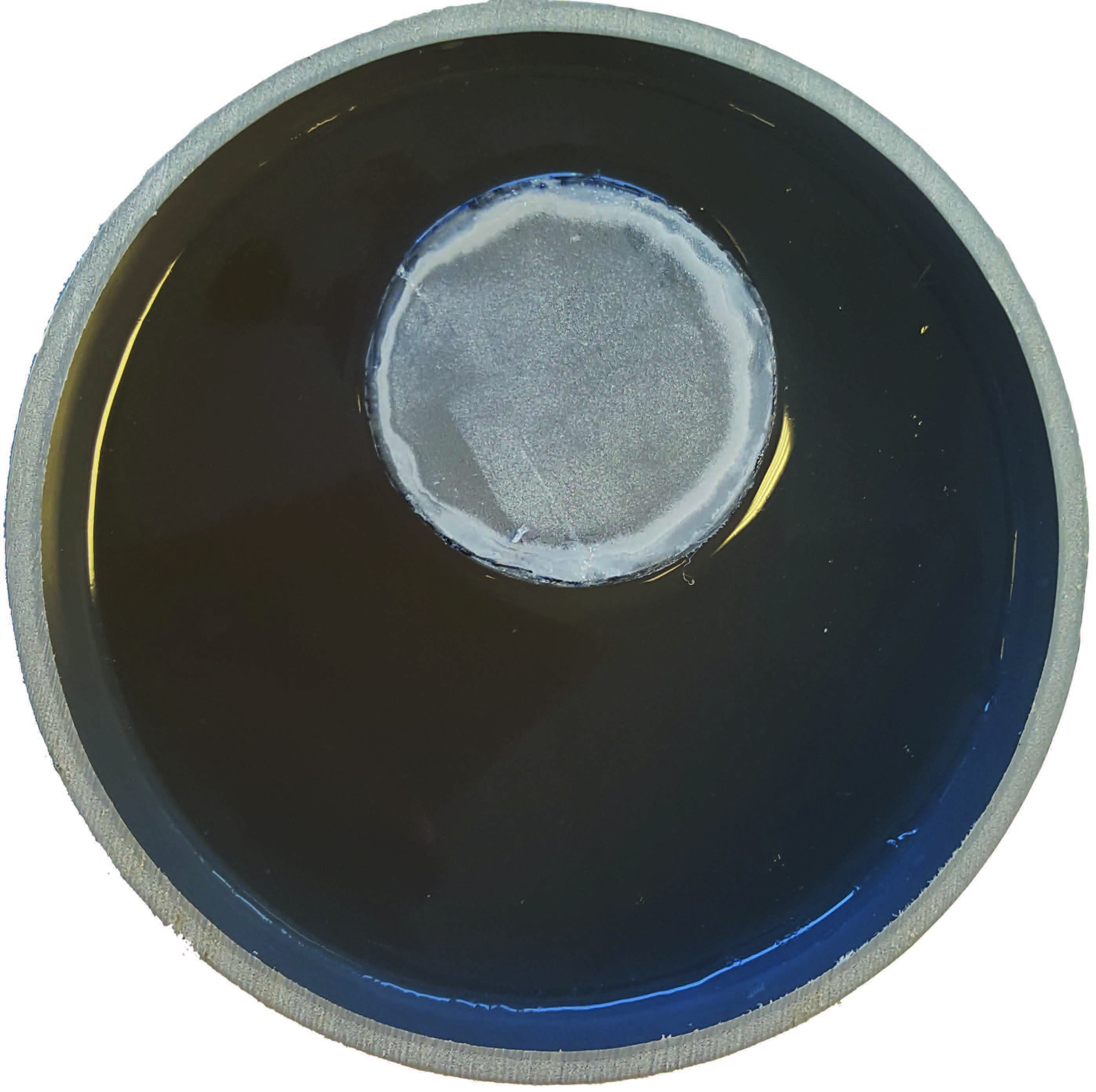
where the asterisk denotes complex conjugation and $$$\omega$$$ is the frequency. To validate our foEPT method, measurements at 3T (Ingenia, Philips) of an agar based conductive phantom (see Figure 1 for image and properties of the phantom) are used. The foEPT conductivity reconstruction is also compared to a standard MR-EPT reconstruction.
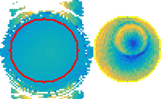
The $$$B_1^+$$$ amplitude (see Figure 2.) of the field was measured using an AFI sequence,8 while the RF transceive phase was measured using two single Spin Echo sequences, thus compensating for eddy currents.9 Both sequences were carried out with an NSA equal to 10, and the mid-plane slice was used. Furthermore, the phantom was placed at the centre and a body coil was used for transmitting, while a head coil (Philips, Eindhoven) was used for reception. The receive array data was phase-referenced to the body coil. Furthermore, to investigate the potential of foEPT for in-vivo permittivity and conductivity mapping of a human brain, simulations of a human head model (ELLA, virtual family10) were performed.
Results and Discussion
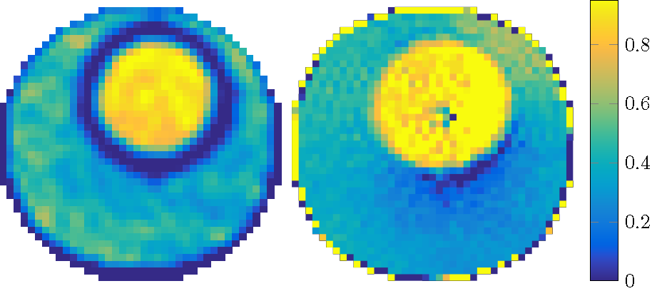
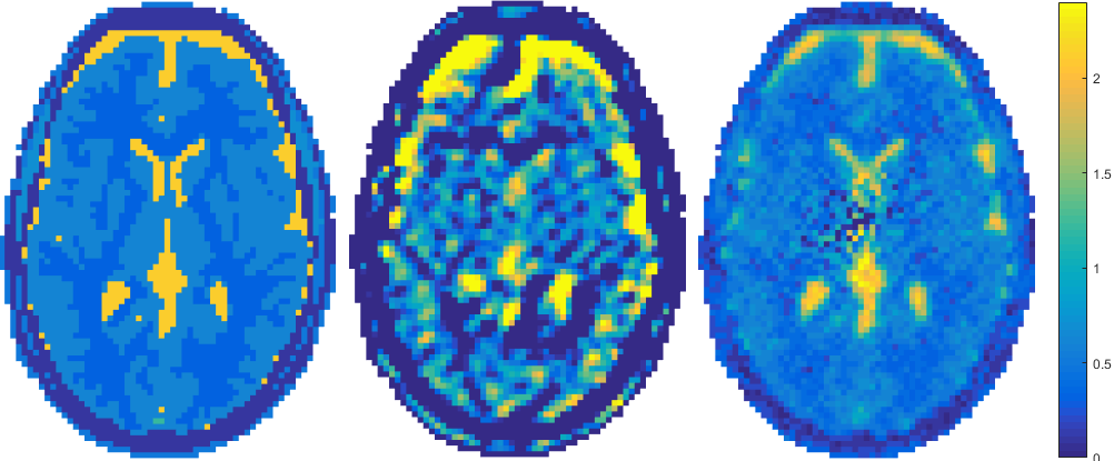
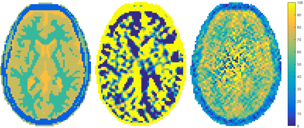
In Figure 3, the reconstruction of the conductivity using the Helmholtz approach (left) as well as the new foEPT method (right) can be seen side by side. We can observe that foEPT enables accurate reconstructions of phantom conductivity without severe artefacts around compartment boundaries compared to the Helmholtz-based reconstruction (Figure 3-left).The reconstructed conductivity also shows a local bias patter near the center and towards the lower right. Current hypotheses for the origin of this artefact point towards either incident field calibration errors, or at the transceive phase assumption. From the simulated reconstructions (Figures 4 and 5) clear advantages in terms of noise amplification and boundary errors for the foEPT method are visible, compared to standard MR-EPT. The noise in the center of the image domain is due to the lower E-field there.Conclusion
These results indicate the potential of the method to reliably reconstructs the conductivity profiles without boundary artefacts, with a better noise tolerance than Helmholtz based methods. Furthermore reconstructions are typically obtained in less than a second on a standard laptop or PC which is a significant speed up compared to global methods. This indicates that foEPT is a promising alternative for in-vivo electrical properties reconstruction.Acknowledgements
The author would like to thank all co-authors for fruitful discussions and suggestions, and the imaging group of the UMC Utrecht and in particular Peter and Stefano for supplying the in-vivo measurements.References
1. U. Katscher, T. Voigt, C. Findeklee, P. Vernickel, K. Nehrke and O. Dossel, “Determination of electrical conductivity and local SAR via B1 mapping,” IEEE Trans. Med. Imaging, vol. 28, no. 9, pp. 1365-1374, 2009.
2. A. L. H. M. W. v. Lier, A. Raaijmakers, T. Voigt, J. J. W. Lagendijk, P. R. Luijten, U. Katscher and C. A. T. v. d. Berg, “Electrical properties tomography in the human brain at 1.5, 3, and 7T: A comparison study,” Magn. Reson. in Med., vol. 71, no. 1, pp. 354-363, 2014.
3. J. Liu, X. Zhang, S. Schmitter, P. v. d. Moortele and B. He, “Gradient-based electrical properties tomography (gEPT): a robust method for mapping electrical properties of biological tissues in vivo using magnetic resonance imaging,” Magn. Reson. Med., vol. 74, no. 3, pp. 634-646, 2015.
4. E. Balidemaj, C. A. T. v. d. Berg, J. Trinks, A. L. H. M. W. v. Lier, A. J. Nederveen, L. .. A. Stalpers, H. Crezee and R. F. Remis, “ CSI-EPT:A contrast source inversion approach for improved MRI-based electrical properties tomography,” IEEE Trans. Med. Imag., vol. 34, no. 9, pp. 1788-1796, 2015.
5. S. Mandija, A. Sbrizzi, U. Katscher, P. R. Luijten and C. A. T. v. d. Berg, “Error analysis of Helmholtz-based MR-Electrical Properties Tomography,” MRM, 2017, early view. DOI 10.1002/mrm.27004.
6. B. v. d. Bergen, C. C. Stolk, J. B. v. d. Berg, J. J. W. Lagendijk and C. A. T. v. d. Berg, “ Ultra fast electromagnetic field computations for RF multi-transmit techniques in high field MRI,” Phys. Med. Biol., vol. 54, no. 5, pp. 1253-1264, 2009.
7. Y. Saad, Iterative methods for sparse linear systems, Philadelphia: Society for Industrial and Applied Mathematics, 2003.
8. V. L. Yarnykh, “Actual flip-angle imaging in the pulsed steady state:A method for rapid three-dimensional mapping of the transmitted radiofrequency field,” Magn. Reson. in Med., vol. 57, no. 1, pp. 192-200, 2007.
9. A. L. H. M. W. v. Lier, D. O. Brunner, K. P. Pruessmann, D. W. J. Klomp, P. R. Luijten, J. W. Langendijk and C. A. T. v. d. Berg, “B1+ phase mapping at 7T and its application for in vivo electrical conductivity mapping,” Magn. Reson. Med., vol. 67, no. 2, pp. 552-561, 2012.
10. A. Christ, W. Kainz, G. E. Hahn, K. Honegger, M. Zefferer, E. Neufeld, W. Rascher, R. Janka, W. Bautz, J. Chen, B. Kiefer, P. Schmitt, P. H. Hollenbach, J. Shen, M. Oberle, D. Szczerba, A. Kam, W. J. Guag and N. Kuster, “The Virtual Family - development of surface-based anatomical models of two adults and two children for dosimetric simulations,” Physics in Medicine and Biology, vol. 55, no. 2, pp. N23-N28, 2010.
11. A. Stogryn, “Equations for Calculating Dielectric Constant of Saline Water,” Ieee Transactions on Microwave Theory and Techniques, vol. 19, no. 8, pp. 733-736, 1971.
Figures