5082
Development of Carbon Electrodes for Current Density Mapping during DBS1SBHSE, Arizona State University, Tempe, AZ, United States
Synopsis
We used MR phase mapping techniques in a preclinical DBS model to image current distributions nearby deep brain stimulation electrodes. To avoid safety issues and artifacts associated with imaging typical platinum-iridium (Pt-Ir) DBS leads, we developed custom carbon electrodes. We compared carbon electrode performance to size-matched Pt-Ir and clinical DBS electrodes at 7 T, using uniform phantoms and fixed brain tissue. Artifacts surrounding carbon electrodes were smaller than for Pt-Ir electrodes. Current density distributions derived from phase images were similar for both electrode types in uniform phantoms and fixed tissue.
Introduction
Neuromodulation therapies such as Deep Brain Stimulation (DBS), are effective in the treatment of neurological disorders1. Analysis of the electric fields established during stimulation could aid in better understanding of neuromodulation mechanisms. We are developing Magnetic Resonance Electrical Impedance Tomography (MREIT) to study field distributions and neural activity (fMREIT) in pre-clinical DBS. Platinum-iridium (90% Platinum, 10% Iridium) has been preferred for fabrication of DBS electrodes2. However, the paramagnetic susceptibility of Pt-Ir (χPt-Ir = 231 ppm) causes local magnetic field inhomogeneities and therefore artifacts around electrodes on magnitude images3. Additionally, the high conductivity of Pt-Ir (σPt-Ir=4x10⁶)4 may lead to inductive heating at higher fields and is a safety concern.
In this study, we tested carbon electrodes (susceptibility χC = -26 ppm, σC = 1x10³ S/m) as an alternative. Artifacts surrounding carbon and Pt-Ir electrodes were compared. We also investigated current distributions using cylindrical DBS and simple carbon electrodes within phantoms. Smaller carbon microelectrodes were then tested in fixed tissue.
Methods
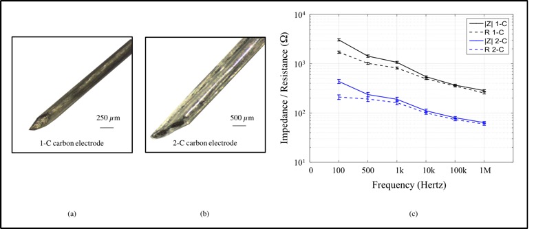
Electrodes - Carbon electrodes were constructed in one-contact (1-C) and two-contact (2-C) configurations (Figures 1(a) and 1(b)). Conductive carbon fibers were dip-coated with solutions of Nafion and Isopropanol (50% V/V) then with Polyvinylidene Fluoride (PVDF) in Acetone (15% W/V). Carbon electrodes were compared with equivalently sized Pt-Ir electrodes. 1-C (ø = 0.27 mm) and 2-C carbon electrodes (width = 1.40 mm) were tested against both Pt-Ir wires (ø = 0.21 mm) and Medtronic 3389 Deep Brain Stimulation leads (ø = 1.27 mm). Impedances of carbon electrodes were measured using an impedance analyzer (HP4192A) and are shown in Figure 1(c).
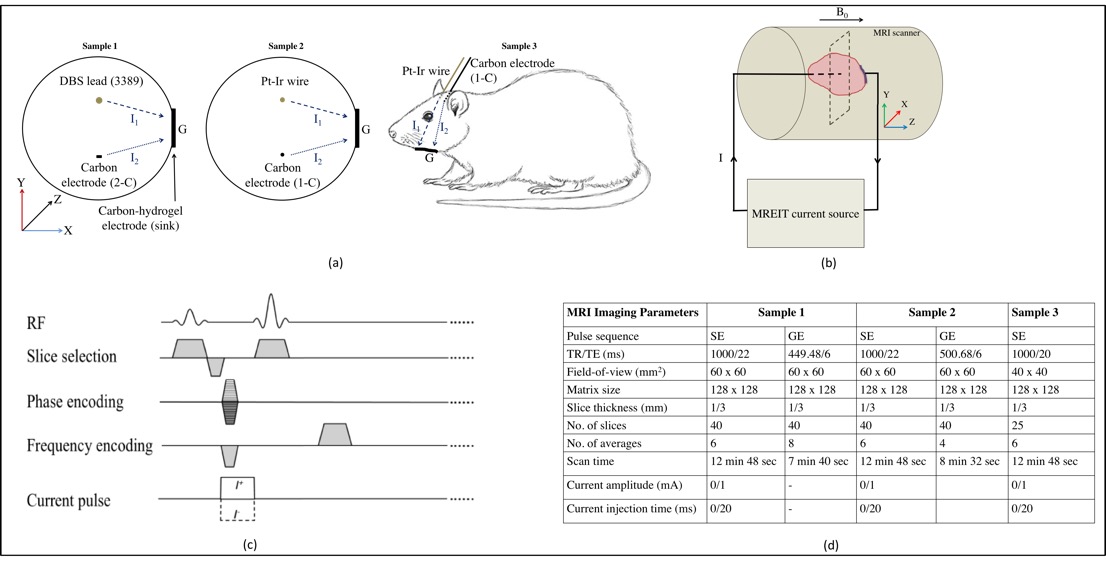
Samples – Cylindrical gel phantoms (ø = 55 mm, height = 42 mm, gel: 20g Agar, 3g NaCl, 0.5g CuSO4, 1000ml Distilled water, σ = 1 S/m) were used to characterize electrodes (samples 1 and 2). A 180 g Wistar rat transcardially perfused with saline containing heparin (1 unit/ml) and 4% paraformaldehyde in 0.1 M Phosphate Buffer was used as sample 3 (Figure 2(a)). A 1-C electrode (ø = 0.30 mm) was implanted at a posterior inclination of 50o into the left hippocampus. Stereotaxic coordinates of the target location were 4.20 mm ML, 3.40 mm anterior and 4 mm dorsal to lambda.
Experimental setup - Imaging experiments were performed in a Bruker Biospin 7T MRI system (Barrow Neurological Institute, USA). Current pulses in MREIT experiments were delivered via carbon or Pt-Ir electrodes oriented parallel to B0 (Figure 2(b)) and external ground electrodes (slice thickness: 3 mm). Current injections were synchronized with spin-echo (SE-MREIT) pulse sequences (Figure 2(c)). Imaging parameters used to acquire MR magnitude images by conventional spin echo (SE) and gradient echo (GRE) pulse sequences (slice thickness: 1 mm) are summarized in Figure 2(d).
Data processing - Full width at half maximum (FWHM) sizes of electrodes on magnitude images were computed. Phase images were scaled to magnetic flux density (Bz)5 distributions and processed to projected current density (JP) distributions6.
Results
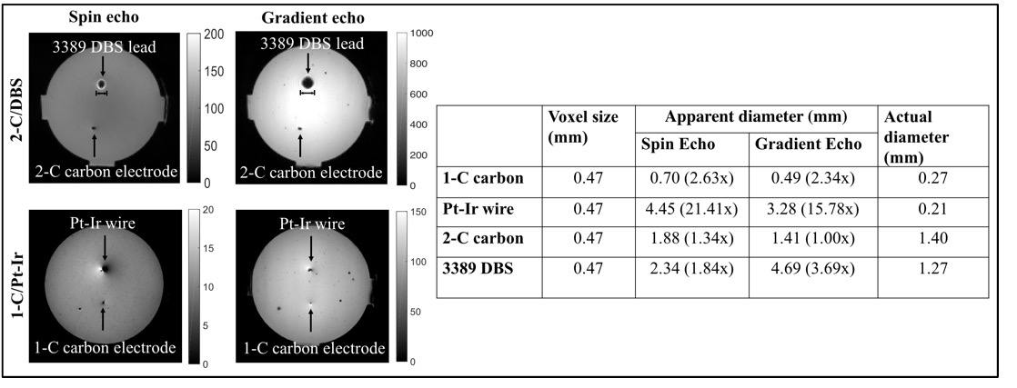
Magnitude images - FWHMs of carbon electrodes were smaller than matched Pt-Ir electrodes (Figure 3). Large artifacts (15.78x) surrounding the smaller Pt-Ir electrode (ø = 0.21 mm) were observed. Small artifacts associated with carbon (~1.00x) improved in GRE acquisitions.
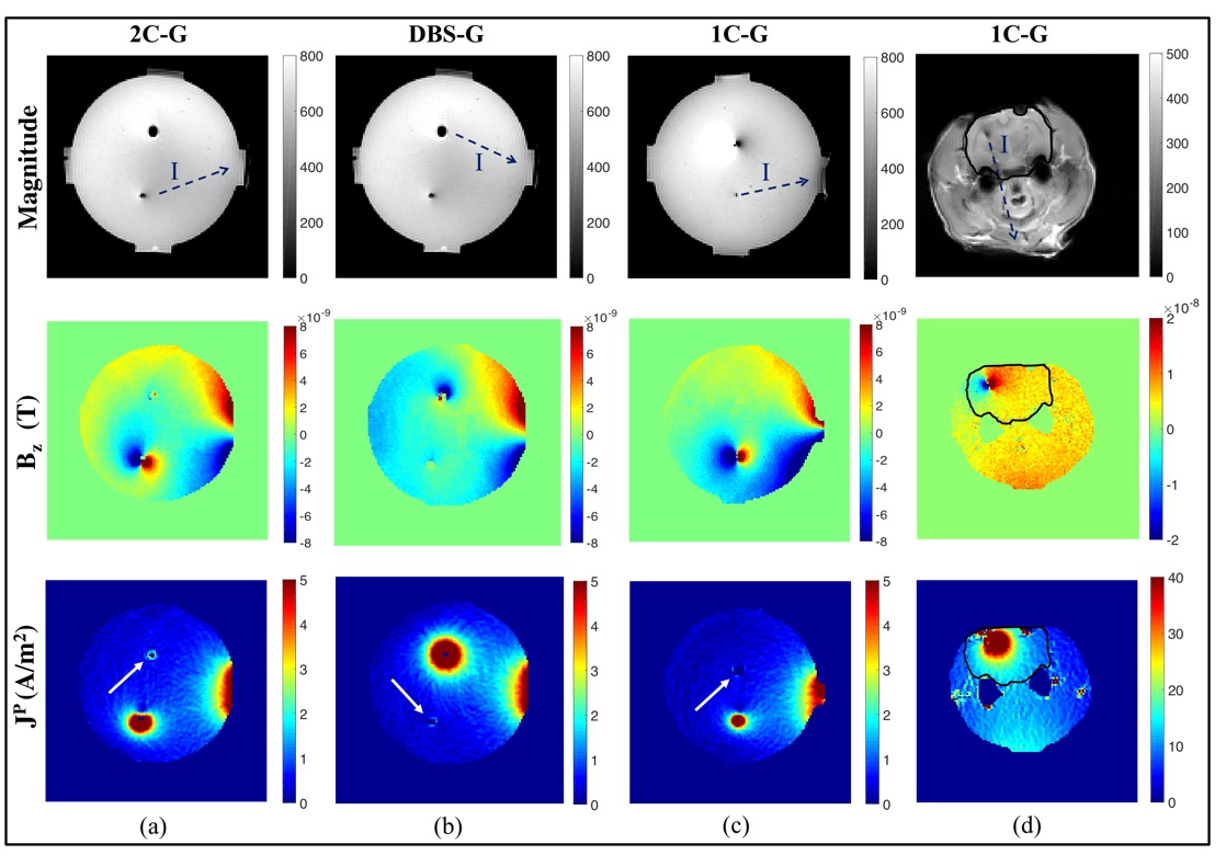
Magnetic flux density (Bz) - Scales of Bz and JP distributions were similar in uniform gel phantoms (Figure 4). Slight misalignments of stimulation electrodes (1-C, 2-C, DBS) contributed to the formation of dipoles in Bz images. Complete dipoles surrounding carbon electrodes were visible in 2C-G and 1C-G electrode pairs. Partial dipoles around the symmetrical DBS lead in DBS-G suggested deviation away from the z-axis. Bz scales in rodent images were 2.50 times larger than in uniform gel phantoms.
Projected current density (Jp) - Current densities surrounding the symmetrical (i.e. cylindrical) DBS lead were symmetrical (Figure 4, last row).
The current density distribution around the rectangular 2-C electrode were
asymmetric, as expected. The smaller effective area of surface electrode (G) and
volume of rodent head increased JP intensities by 8 times compared
to gel phantoms.
Discussion
The almost negligible artifacts around smaller carbon electrodes (1-C) in GRE suggests carbon microelectrodes are well suited for use with faster sequences and high magnetic field strengths. The appearance of non-stimulating electrodes (arrows in Figure 4) in Bz and JP images demonstrated local concentrations of current in high conductivity regions.
Conclusion
The low susceptibility of carbon resulted in smaller artifacts in MR images. The development of carbon electrodes facilitates current density mapping around DBS electrodes. Carbon is a superior choice to conventional Pt-Ir for current delivery in magnetic fields. Future work will involve electrode geometry optimization.Acknowledgements
No acknowledgement found.References
1. Benabid, A.L., Charbardes, S., et al. Deep brain stimulation of the subthalaic nucleus for the treatment of Parkinson's disease. Lancet Neurology, 2009; 8(1):67-81.
2. Cogan, S.F. Neural stimulation and recording electrodes. Annu Rev Biomed Eng, 2008; 10:275-309.
3. Jiang, C.Q., Hao, H.W., et al. Artifact properties of carbon nanotube yarn electrode in magnetic resonance imaging. J Neural Eng, 2013; 10(2):026013.
4. Matthey, Johnson, et al. The PGM Database. September 26 2017.http://www.pgmdatabase.com/jmpgm/index.jsp?record=1064.
5. Woo, E.J., & Seo, J.K. Magnetic resonance electrical impedance tomography (MREIT) for high-resolution conductivity imaging. Physiol Meas, 2008; 29(10):R1-R26.
6. Nam, H.S., Park, C. et al. Non-iterative conductivity reconstruction algorithm using projected current density in MREIT. Phys Med Biol, 2008; 53(23):6947-6961.
Figures