4884
Second-order motion-compensated in-vivo cardiac diffusion tensor imaging in diastole – impact of ventricular flow, strain and trigger delay.1Institute for Biomedical Engineering, University and ETH Zürich, Zürich, Switzerland
Synopsis
Motion-compensated spin-echo cardiac diffusion tensor imaging (cDTI) sequences suffer from signal loss if the motion pattern has higher-order motion terms than the motion compensation model of the encoding gradients. Particularly cardiac strain, ventricular flow and atrial contraction render diffusion imaging in diastole challenging. It is shown that a suitable trigger delay in the diastolic phase can be identified by taking into account ventricular flow, strain and diffusion-weighted data at several time points in diastole. This knowledge aids towards the development of spin-echo-based cDTI sequences to study dynamic myofiber changes between systole and diastole.
Introduction
Second-order motion-compensated spin-echo (M2-SE) sequences have been proposed for in-vivo cardiac diffusion tensor imaging1-3, yielding improved SNR efficiency relative to stimulated-echo acquisition mode (STEAM) based sequences4. Although the M2-SE sequence has shown to work successfully in systole1, imaging in the diastole remains challenging. Cardiac jerk and higher-order motion terms, interaction of the myocardium with ventricular inflow, or atrial contraction can lead to signal dephasing when diffusion gradients are applied. As a result, defining a suitable trigger delay (TD) solely based on visual assessment of cine data might be insufficient. The goal of the current work is to identify an optimal time window for cDTI in diastole by assessing ventricular flow and circumferential strain.Methods
Data acquisition
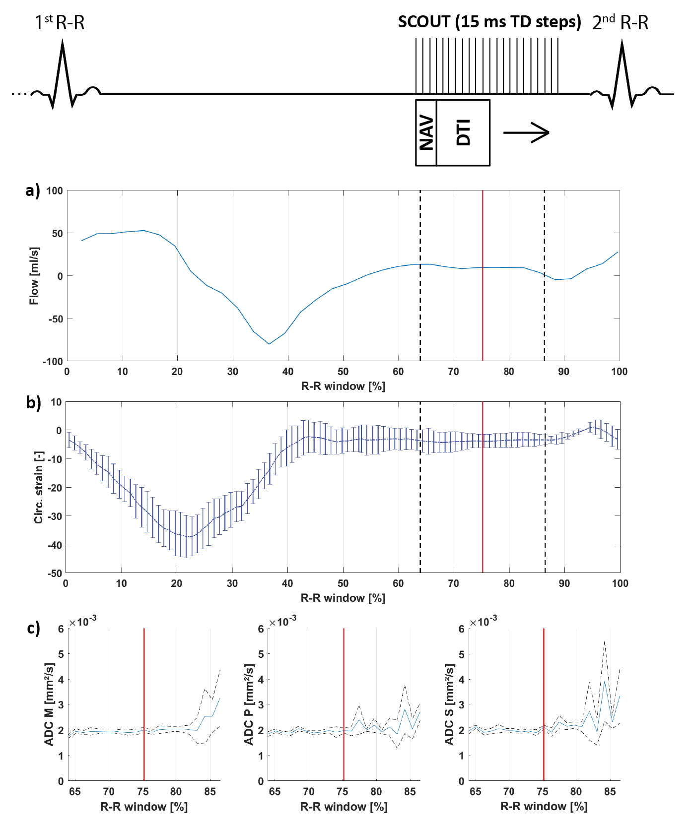
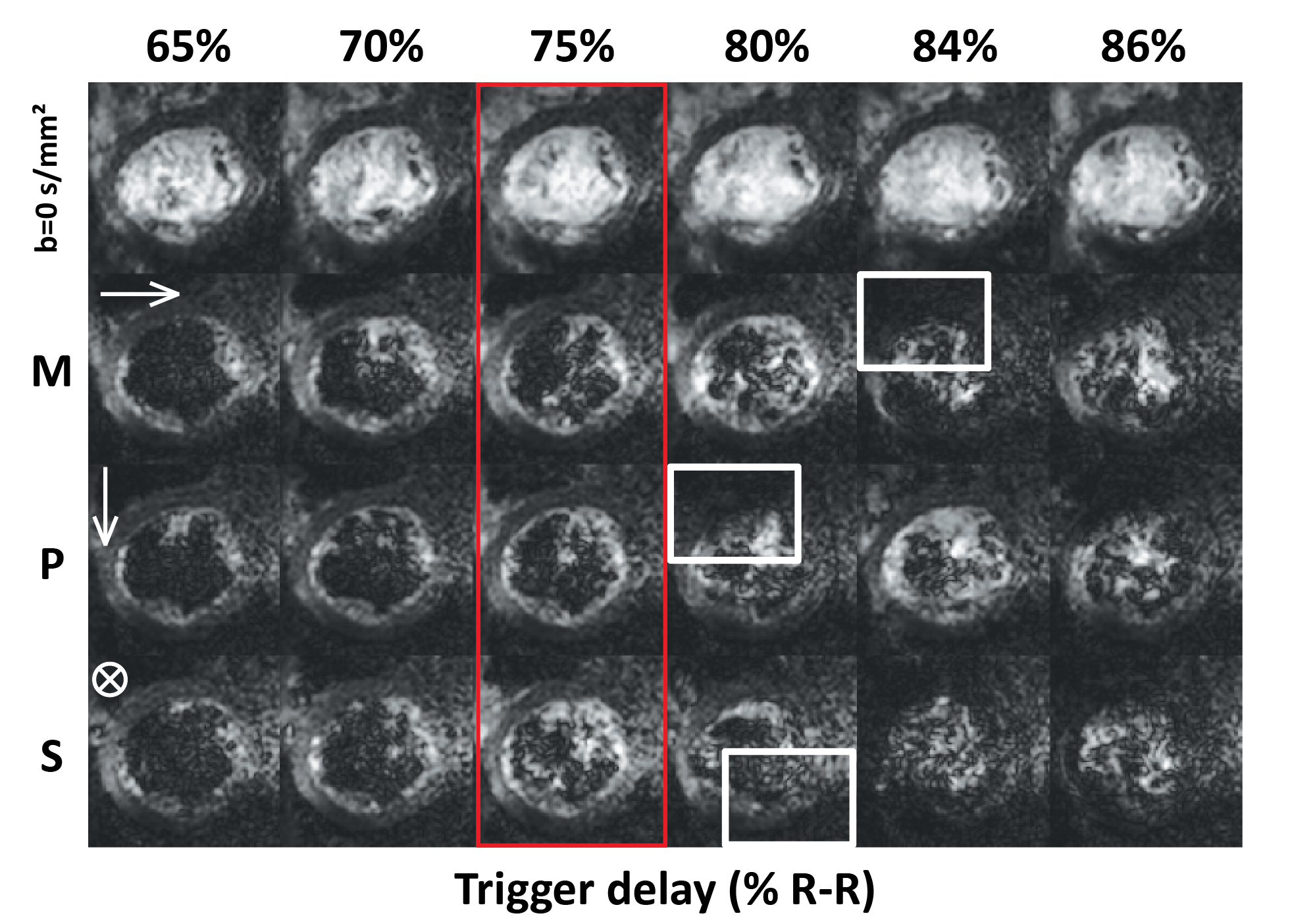
All scans were performed on a 1.5T clinical MR system (Philips Healthcare, Best, The Netherlands) using a 32-channel cardiac receiver array and a gradient system delivering 80mT/m@100mT/m/ms. Data acquisition was triggered to a pulse-oximeter unit and performed during navigator gated (5 mm gating window) breath holding. A single slice DWI scout scan, a 2D flow scan (spatial/temporal resolution: 2.2×2.2×10mm3/35ms), and a CINE scan (spatial/temporal resolution: 2x2x15mm3/12ms) were acquired in short-axis view orientation at mid-ventricular level. The DWI scan consisted of an unweighted image and three DWIs with diffusion-weighting applied in 3 orthogonal directions (b=350 s/mm²). After choosing a diastolic TD based on visual inspection of signal voids in the DWI scout (Figure 1) and the mean ventricular flow velocity measured in the left ventricular blood pool, a DTI scan was performed with diffusion-weighting of b=100 s/mm² along three orthogonal directions and b=350 s/mm² along 6 directions. Imaging parameters for the DWI and DTI were: spatial resolution 2.0x2.0 mm², slice thickness 8 mm, reduced-FOV5 230x111 mm², SENSE-factor 1.5, TR/TE = 1 R-R/82 ms, signal averages (DWI scout/DTI) 4/16. The DWI scout employed a range of trigger delays of 300-400 ms with 15 ms increments, and was initiated at the plateau of diastolic ventricular flow velocity (Figure 1). Diffusion directions were fixed to the image coordinate system. Three healthy volunteers (2 male, HR 55±6 beats/min, age 34±11 years) were imaged upon written informed consent.
Data analysis
2D flow data was processed using GTFlow (GyroTools LLC, Winterthur, Switzerland) to obtain mean velocity data. Circumferential strain was computed from the CINE scans using dedicated software (TomTec Imaging Systems, Unterschleissheim, Germany). Apparent diffusion coefficient (ADC) maps were computed for each different trigger delay of the DWI scout scan of which the left-ventricular myocardium was manually segmented. Images were aligned using non-rigid image registration6. An acceptance window for ADC was defined by the minimum ADC plus 25% of the mean ADC across volunteers within 70% to 80% of the R-R window. After calculation of the diffusion tensors, helix angle (HA), transverse angle (TA), absolute E2A sheet angles (absE2A), mean diffusivity (MD), and fractional anisotropy (FA) were estimated7-9.
Results
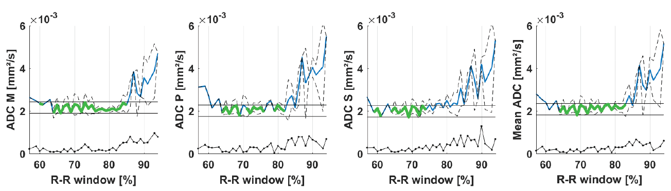
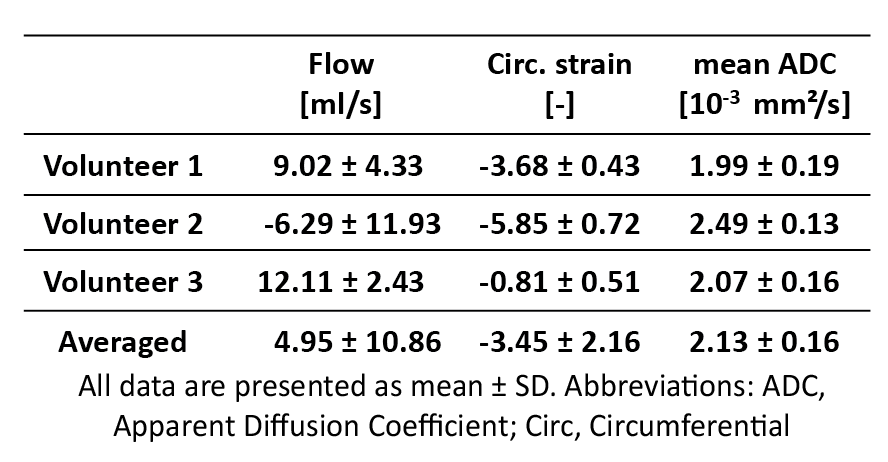
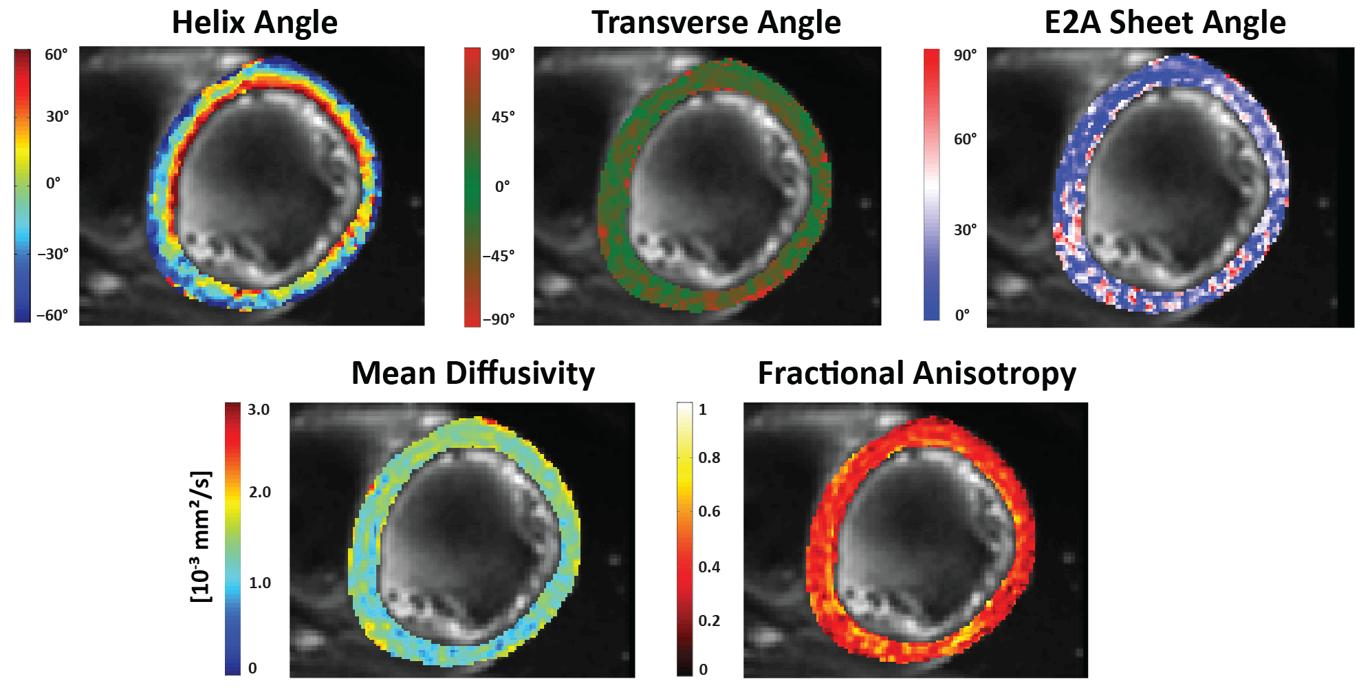
Figure 1 shows myocardial flow and strain as well as ADCs as a function of trigger delay. A plateau can be observed in both flow and strain data during the diastolic imaging window. Corresponding ADC data shows stable behavior between 65% and 75% R-R window for in-plane and through-plane directions (Figure 2), but rapidly changes beyond 85% R-R window. Figure 3 shows the inter-volunteer reproducibility of ADC measurements. The diastolic imaging window was identified as 64% to 83% of the R-R window, in which beat-to-beat variation is relatively stable (1.90·10-4 mm²/s). The corresponding flow, circumferential strain, and mean ADC values within this window are 5.97±11.21 ml/s, -3.45±2.25, 2.13±0.16·10-3 mm²/s, respectively, and can be found in Table 1. Example angulation and MD/FA maps acquired at 75% R-R window are shown in Figure 4. Average angulation parameters and TD across volunteers were: MD (1.37±0.37 10-3 mm²/s), FA (0.42±0.18), HAG (-1.07±0.20°/%depth), TA (-0.55±18.15°), absE2A (30.95±22.03°), and TD (73.33±4.73 % R-R window).Discussion
Using additional information regarding ventricular flow and circumferential strain, an imaging window could be identified to successfully acquire DTI data in diastole using the M2-SE sequence. An increase in ADC starting around a TD of 80-95% R-R% may be attributed to changes in flow and respective passive motion of the ventricular myocardium, coinciding with the time point of atrial contraction. ADC values were increased compared to MD, potentially due to perfusion effects10. Diffusion metrics and angle maps are in agreement with existing literature11-12. The heart-rate dependency of the diastolic window and inter-subject differences pose acquisition challenges and require the TD to be assessed per subject.Acknowledgements
No acknowledgement found.References
[1] C. T. Stoeck, C. von Deuster, M. Genet, D. Atkinson, and S. Kozerke, “Second-order motion-compensated spin echo diffusion tensor imaging of the human heart.,” Magn. Reson. Med., May 2015.
[2] C. Nguyen, Z. Fan, B. Sharif, Y. He, R. Dharmakumar, D. S. Berman, and D. Li, “In Vivo Three-Dimensional High Resolution Cardiac Diffusion-Weighted MRI : A Motion Compensated Diffusion-Prepared Balanced Steady-State Free Precession Approach,” Magn. Reson. Med., vol. 72, pp. 1257–1267, 2014.
[3] C. Nguyen, Z. Fan, Y. Xie, J. Pang, P. Speier, X. Bi, J. Kobashigawa, and D. Li, “In Vivo Diffusion-Tensor MRI of the Human Heart on a 3 Tesla Clinical Scanner : An Optimized Second Order ( M2 ) Motion Compensated Diffusion-Preparation Approach,” Magn. Reson. Med., vol. 76, pp. 1354–1363, 2016.
[4] C. von Deuster, C. T. Stoeck, M. Genet, D. Atkinson, and S. Kozerke, “Spin echo versus stimulated echo diffusion tensor imaging of the in vivo human heart,” Magn. Reson. Med., vol. 76, pp. 862–872, 2016. [5] C. Reischauer, B. J. Wilm, J. M. Froehlich, A. Gutzeit, L. Prikler, R. Gablinger, P. Boesiger, and K. U. Wentz, “High-resolution diffusion tensor imaging of prostate cancer using a reduced FOV technique,” Eur. J. Radiol., vol. 80, no. 2, pp. 34–41, 2011.
[6] V. Vishnevskiy, T. Gass, G. Szekely, C. Tanner, and O. Goksel, “Isotropic Total Variation Regularization of Displacements in Parametric Image Registration,” vol. 36, no. 2, pp. 385–395, 2017.
[7] P. F. Ferreira, P. J. Kilner, L.-A. McGill, S. Nielles-Vallespin, A. D. Scott, S. Y. Ho, K. P. McCarthy, M. M. Haba, T. F. Ismail, P. D. Gatehouse, R. de Silva, A. R. Lyon, S. K. Prasad, D. N. Firmin, and D. J. Pennell, “In vivo cardiovascular magnetic resonance diffusion tensor imaging shows evidence of abnormal myocardial laminar orientations and mobility in hypertrophic cardiomyopathy.,” J. Cardiovasc. Magn. Reson., vol. 16, p. 87, 2014.
[8] J. S. D.F, H. Alex, W. Raimond, and Forder, “Histological validation of myocardial microstructure obtained from diffusion tensor magnetic resonance imaging,” Am. J. Physiol. Heart Circ. Physiol., vol. 275, no. 3, pp. 2308–2318, 1998.
[9] C. T. Stoeck, A. Kalinowska, C. Von Deuster, J. Harmer, R. W. Chan, M. Niemann, R. Manka, D. Atkinson, D. E. Sosnovik, C. Mekkaoui, and S. Kozerke, “Dual-phase cardiac diffusion tensor imaging with strain correction,” PLoS One, vol. 9, no. 9, pp. 1–12, 2014.
[10] D. Le Bihan, E. Breton, D. Lallemand, P. Grenier, E. Cabanis, and M. Laval-Jeantet, “MR imaging of intravoxel incoherent motions: application to diffusion and perfusion in neurologic disorders.,” Radiology, vol. 161, pp. 401–407, 1986.
[11] A. D. Scott, S. Nielles-Vallespin, P. Ferreira, Z. Khalique, L.-A. McGill, P. J. Kilner, D. J. Pennell, and D. Firmin, “In-vivo cardiac DTI: An initial comparison of M012 compensated spin-echo and STEAM,” in Journal of Cardiovascular Magnetic Resonance, 2016, vol. 18, no. Suppl 1, p. W19.
[12] S. Nielles-vallespin, Z. Khalique, P. F. Ferreira, R. De Silva, A. D. Scott, P. Kilner, L. Mcgill, A. Giannakidis, P. D. Gatehouse, D. Ennis, E. Aliotta, M. Al-khalil, P. Kellman, D. Mazilu, R. S. Balaban, D. N. Firmin, A. E. Arai, and D. J. Pennell, “Assessment of Myocardial Microstructural Dynamics by In Vivo Diffusion Tensor Cardiac Magnetic Resonance,” vol. 69, no. 6, 2017.
Figures