4822
A cost effective, 3D printed vasculature phantom for MR imaging of stroke1Medical Imaging Research Centre, Dayananda Sagar Institutions, Bangalore, India, 2Department of Radiology, Columbia University Medical Centre, New York, NY, United States
Synopsis
Stroke is mainly caused due to hemorrhage or ischemia due to infarct. Current work aims to develop a phantom which can mimic structure and function of a human brain stroke using 3D print technology. The normal human brain vasculature was printed using Poly Lactic Acid. An ischemic infarct was mimicked using Poly Vinyl Alcohol and a cerebral aneurysm was integrated to the vasculature to demonstrate simultaneous onset of hemorrhagic and ischemic stroke. Waterflow to the phantom was introduced by integrating the peristaltic pump. T1, T2 , DW images and T 1and T2maps were generated which depict the stroke vasculature
Introduction
Stroke is the 5th leading cause of death and long-term disability in the US1. Ischemic stroke is the most frequent cause of stroke and is responsible for 80% of strokes while 30% of them are caused due to hemorrhage2. Simultaneous onset of hemorrhagic and ischemic stroke has also been reported3. The current work aims to develop a phantom, which can mimic structure and function of a human brain stroke using 3D print technology.Materials & Methods
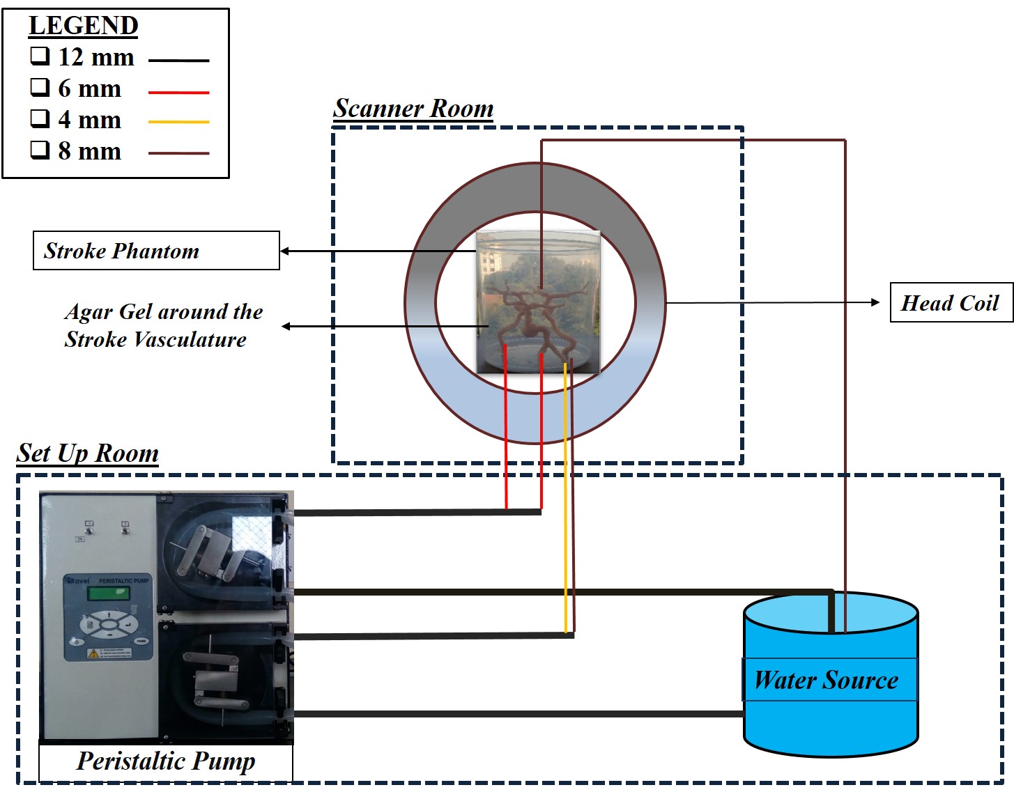
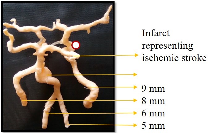
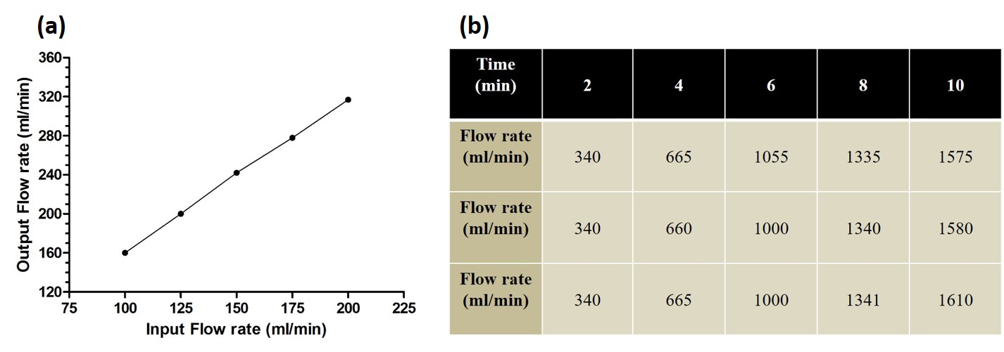
STereoLithography (STL) model of a normal human brain vasculature representing the arterial system was downloaded from ref4. The phantom was made of Poly Lactic Acid (PLA) thermoplastic material using Dimension Dual Delta 3D printer (J Robotics Pvt. Ltd). The major components of the entire setup included the peristaltic pump, agarose gel, silicon pipes and the printed stroke phantom. The total cost of this entire phantom was $1,400 (USD). A scaling factor of 200% was set to obtain dimension similar to human brain vasculature. The total printing time was approximately 12hours. STL model of aneurysm was downloaded from ref5 and printed separately using PLA. An aneurysm was introduced in the vasculature at the basilar artery as it represents 7% of cerebral aneurysms6. A 12cm3 infarct core was prepared using Poly Vinyl Alcohol (PVA). The concentration of PVA was chosen as 16% (w/v) to mimic infarct core with an ADC value of approximately 630±68*10-6 mm2/s7. The PVA was placed at the clinoid segment of the left carotid artery to represent an internal carotid artery ischemia8. The phantom was later placed in a plastic cylindrical container and filled with agarose gel of concentration 1.25% (w/v) to mimic surrounding normal brain tissues9. The stroke phantom was integrated with a peristaltic pump using silicon pipes of different dimensions as shown in Figure 1. Four pipes were connected as input at the bottom of the vasculature and one pipe was connected as output from the top of the vasculature. The water was then drawn from and collected in the reservoir. Flow rate was varied from 100 to 200 in steps of 25 ml/min to determine the optimized flow rate. The forward time of the pumps was set to 1 minute while the reverse time was set to 0. The output was collected in a container and measured using a measuring cylinder. MR data of the phantom data was acquired on a 1.5T Siemens Avanto scanner. Protocol included a sagittal T1 weighted variable flip angle based sequence with TR/TE of 7/1.56ms, FA of 5°, a Turbo spin echo based T2 weighted sequence with TR/TE of 3000/22ms, a Diffusion weighted Spin echo EPI based sequence with TR/TE of 3600/102ms, Time-Of-Flight angiography with TR/TE of 25/7ms and FA of 25° and T1 MPRAGE sequence with TR/TE of 650/2.99ms.Results & Discussion
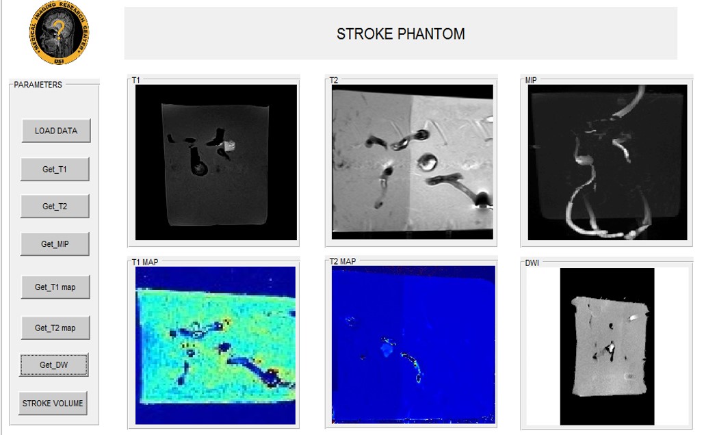
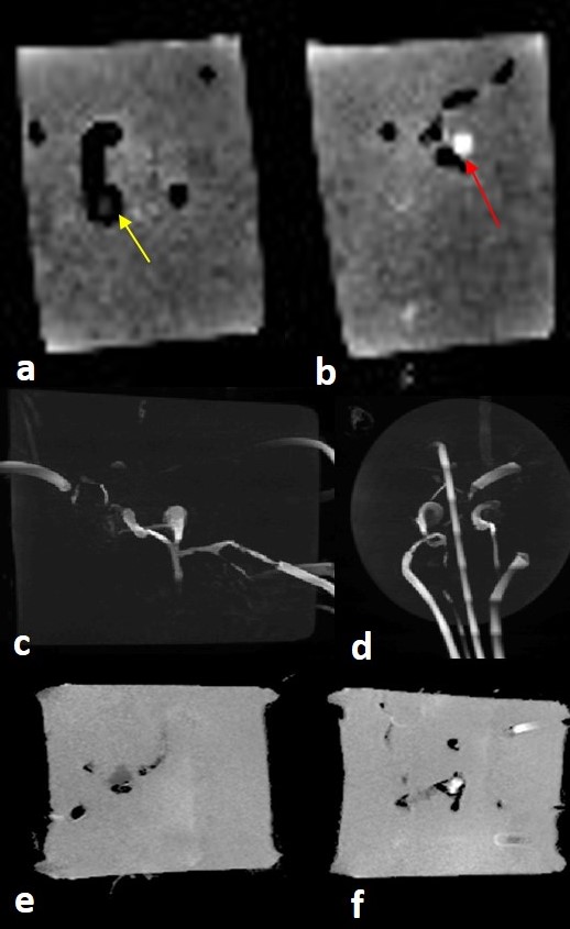
Figure 2 shows the 3D printed stroke phantom. Figure 3a shows the variation of output for varying input flow rate. Five experiments were subsequently conducted to evaluate the optimized flow rate with a time variation of 2 minutes in three iterations and the results are as shown in Figure 3b. Figure 4 shows the UI depicting T1, T2, Diffusion weighted and Maximum Intensity Projection (MIP) images and T1, T2 maps obtained from the phantom. Figure 5a and 5b shows the resultant MPRAGE image depicting the aneurysm, which is pointed in yellow and the infarct core pointed in red respectively. Figures 5c and 5d show the MIP from sagittal and coronal slice orientations. Figures 5e and 5f depict the infarct and the aneurysm of the stroke phantom from a DW image respectively.
From Figure 3a, it is observed that a flowrate of 100ml/min provides a minimal error of 40ml and hence was chosen for the experiments. Figure 5e shows that the infarct is hyperintense on a DW image due to increased water flow. However, the aneurysm as shown in figure 5f is hypointense due to restricted water flow as expected in the case of a hemorrhage and an ischemic infarct. Flow rate of 100ml/min causes insufficient flow to the vasculature which results in reduced signal intensity as observed in the images.
Conclusion
Human brain vasculature depicting hemorrhage and infarct core has been demonstrated. This phantom could be used to validate novel stroke acquisition and reconstruction strategies. 3D print technology enables development of patient specific vasculature for surgical planning. Future work involves in optimization of the phantom to mimic a blood flow rate of 750ml/min in the brain.Acknowledgements
Department of Science and Technology(DST). DST/TSG/NTS/2013/100References
[1] Mozaffarian, Dariush, Emelia J. Benjamin, Alan S. Go, Donna K. Arnett, Michael J. Blaha, Mary Cushman, Sandeep R. Das et al. "Executive Summary: Heart Disease and Stroke Statistics-2016 Update: A Report From the American Heart Association." Circulation 133, no. 4 (2016): 447.
[2] Basics, Brain. "Preventing Stroke". National Institute of Neurological Disorders and Stroke." (2009).
[3] Balci, Kemal, Ufuk Utku, Talip Asil, and Ercument Unlu. "Simultaneous onset of hemorrhagic and ischemic strokes." The neurologist 13, no. 3 (2007): 148-149.
[4] http://www.thingiverse.com/thing:1233389
[5] https://www.embodi3d.com/files/file/110-splenic-artery-aneurysms-hollow-model-stl-file/
[6] Brisman, Jonathan L., Joon K. Song, and David W. Newell. "Cerebral aneurysms." New England Journal of Medicine 355.9 (2006): 928-939.
[7] Oppenheim, Catherine, Cécile Grandin, Yves Samson, Anne Smith, Thierry Duprez, Claude Marsault, and Guy Cosnard. "Is there an apparent diffusion coefficient threshold in predicting tissue viability in hyperacute stroke?." Stroke 32, no. 11 (2001): 2486-2491.
[8] Fritz, VIVIAN U., CHRIS L. Voll, and LEWIS J. Levien. "Internal carotid artery occlusion: clinical and therapeutic implications." Stroke 16, no. 6 (1985): 940-944.
[9] Laubach, Hans, Peter M. Jakob, Karl O. Loevblad, Alison E. Baird, Maria Picone Bovo, Robert R. Edelman, and Steven Warach. "A Phantom for diffusion‐weighted imaging of acute stroke." Journal of Magnetic Resonance Imaging 8, no. 6 (1998): 1349-1354.
Figures