4761
Reconstruction of the 12-lead ECG using a novel MR-compatible ECG sensor network1Schiller Medical SAS, Wissembourg, France, 2IADI, INSERM U947 and Université de Lorraine, Nancy, France, 3CIC-IT 1433, INSERM, Université de Lorraine and CHRU Nancy, Nancy, France
Synopsis
Currently patient monitoring and sequence triggering during MR imaging are achieved using a low bandwidth ECG of 1Hz-60 Hz. Such devices provide a limited number of ECG leads and thus do not provide the same diagnostic information as the standard 12-lead ECG. In this work we developed a high-bandwidth MR-compatible ECG sensor (0.05Hz – 150 Hz) that integrates real-time signal processing for ECG denoising. Several individual sensors are combined to reconstruct a 12-lead ECG during MR imaging. The system was tested on a volunteer at 1.5T and could be used during MR-guided intervention or for inverse ECG imaging.
INTRODUCTION
Currently, ECG devices used in MRI for patient monitoring and sequence triggering do not provide a standard 12-lead ECG. Due to physics constraints, the ECG bandwidth is limited to 1Hz-60Hz 1, 2 and a reduced number of leads is available. An MR-conditional 12-lead ECG device has been proposed for interventional MRI 3, however this technology was based on a single sensor with long carbon fiber cables, which does not eliminate the risk of radiofrequency (RF) heating in worst case MRI sequences. In this work we propose an alternative technology that uses a network of novel small-sized MR-compatible ECG sensors. Each of these sensors has a large bandwidth (0.05Hz – 150 Hz) and includes real-time denoising 4. Furthermore, a method is presented for 12-lead ECG reconstruction. Phantom tests were performed to evaluate RF-induced heating in worst-case scenarios. We then showed the feasibility of the 12-lead ECG reconstruction during MRI in volunteers.MATERIALS AND METHODS
ECG sensor network
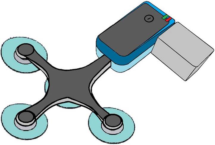
The sensor network is composed of N (N=4 in this study) independent MR-compatible ECG sensors (prototype developed for research use, based on the Maglife technology, Schiller Médical, Wissembourg, France) as shown in Figure 1. Each sensor is composed of a short flexible triple-branch wire, molded with biocompatible silicon, connecting four surface electrodes (one common lead reference electrode + three measurement electrodes) to the sensor box. The device provides three independent bipolar ECG leads with a 0.05Hz-150Hz bandwidth. It also embeds three Hall effect probes (X,Y,Z) for local magnetic field measurements (during MR gradient switching). Real-time signal processing is performed on a microcontroller, including MR-gradient artifact cancellation 4 and QRS detection. The signals are finally transferred by optical fiber to a computer for recording and analysis.
12-lead ECG reconstruction
The 12-lead ECG is reconstructed using a method similar to Refs 5, 6, using a linear transformation of the signals from the sensor network, as described by a matrix M in the equation below :
$$S_{12 Lead}(t)=M\times\beta_{Lead Network}(t)$$
The M matrix is determined on a subject-specific basis. It is generated after a calibration step, which consists of matching the sensor network linear combinations to a template PQRST waveform, recorded prior to the MRI session (i.e. in the patient preparation room), with a conventional 12-lead device (Physiogard touch 7, Schiller Médical, Wissembourg, France).
MR-compatibility experiments
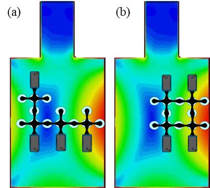
MR-compatibility of the sensor network was determined based on RF heating tests with an ASTM phantom following the CEI 60601-2-33 standard, on a Discovery MR750 3T scanner (General Electric, Milwaukee, USA). Two spatial configurations of the sensors were tested and electrodes were shared between the individual sensors in order to maximize the antenna effect (see Figure 2). The sensors were placed in a way to maximize the tangential electric field as shown in Figure 2.
Volunteer experiments
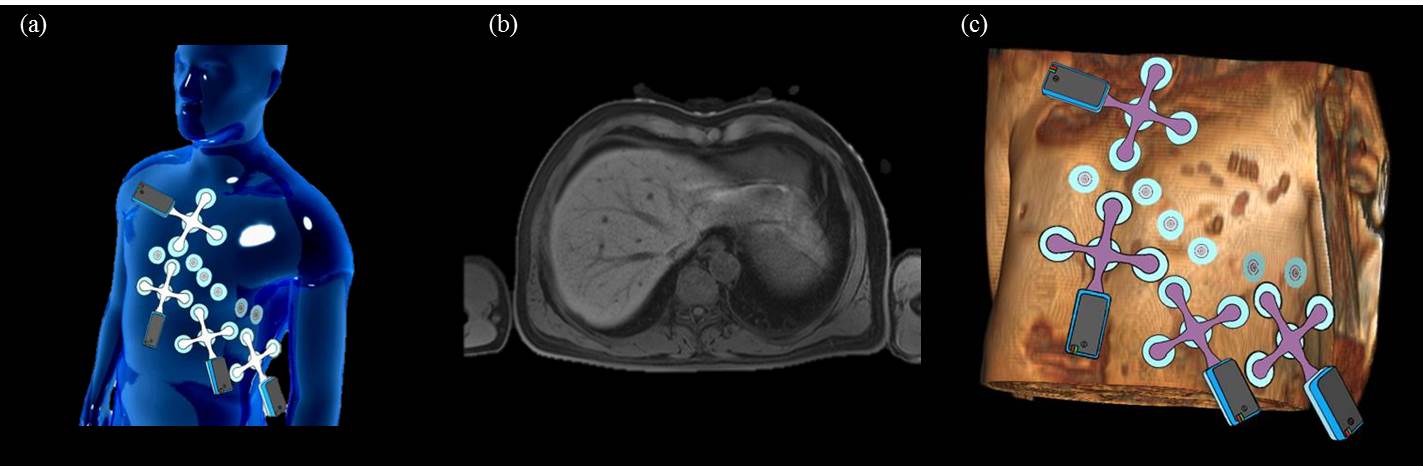
ECG was acquired on two healthy volunteers in a 1.5T AvantoFit scanner (Siemens, Erlangen, Germany). A total of 26 MR-compatible electrodes were placed on the chest (16 for the sensor network + 10 for the 12-lead ECG calibration, see Figure 3). The acquisition protocol consisted of 3 steps: (i) acquisition in the preparation room (sensor network + 12-lead system) to calibrate the M matrix; (ii) acquisition inside the MRI bore with no sequence played (sensor network only); (iii) acquisition during MRI sequences. The MRI protocol included a 3D T1-weighted Dixon sequence (axial VIBE, FOV 410x410x350 mm3, 1.2x1.2x4 mm3) to provide a 3D torso model and localize the electrodes, and a balanced SSFP sequence (TRUFI Cine) to test the sensor during a commonly used cardiac sequence.
RESULTS
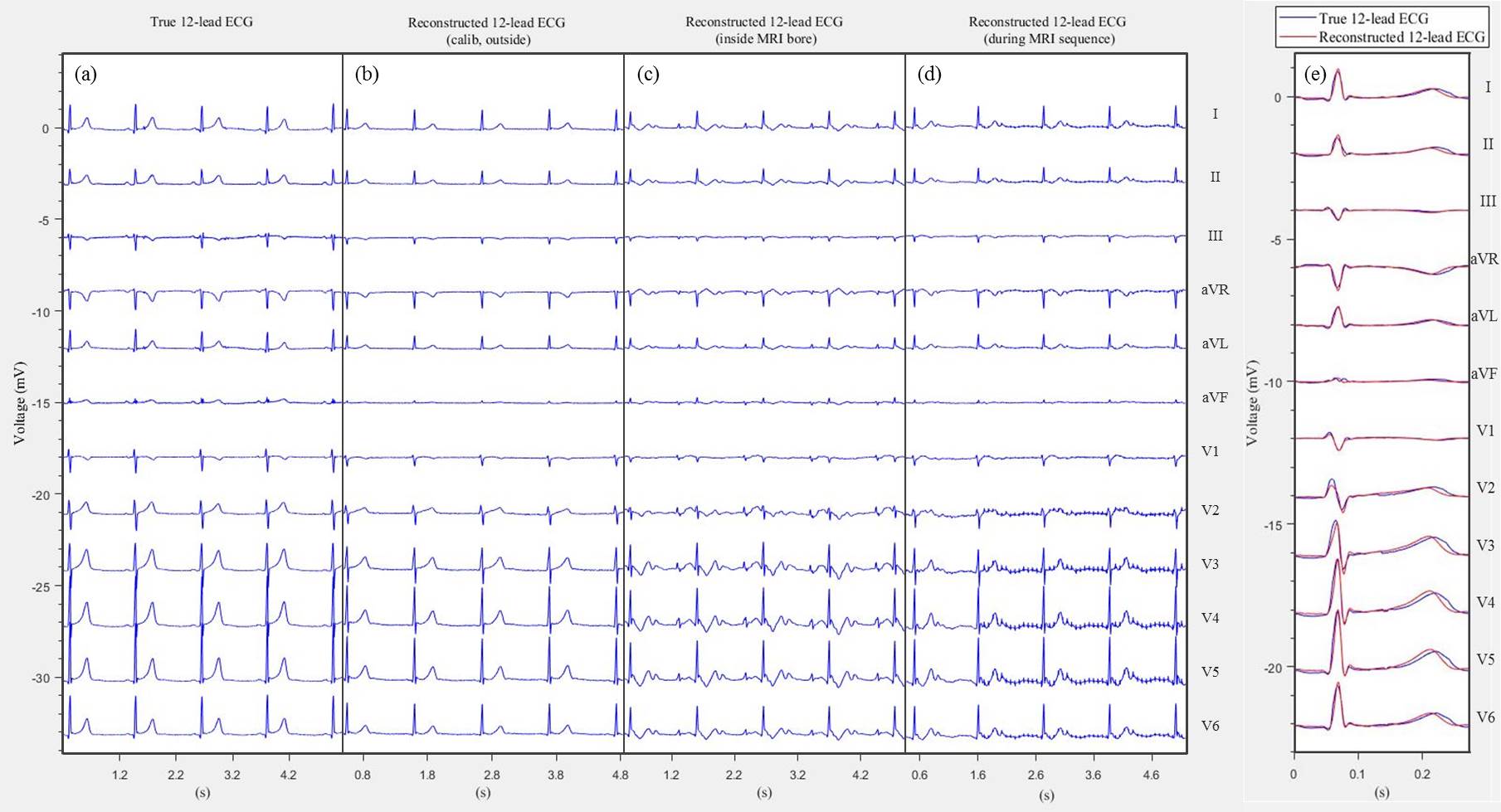
The temperature elevation in the phantom was between 1.2°C and 4.6°C (configuration a), and between 2.4°C and 4.7°C (configuration b). Figure 4 shows an example reconstruction of the synthetic 12-lead ECG. The reconstructed 12-lead ECG, outside the scanner, shows good agreement with the conventional 12-lead ECG, with an accurate morphology for the principal waves (Q, R, S, T). Inside the magnet, the ECG is distorted due to the added magneto-hydrodynamic (MHD) effect. During the SSFP sequence, small-amplitude gradient-switching artifacts are also observed (after filtering to a 0.05-120 Hz bandwidth in this example).DISCUSSION AND CONCLUSION
The measured temperature elevations were below the thresholds defined by the CEI 60601-2-33 standard (43°C for devices in contact with skin, skin temperature being in the range 33-37°C). Results in volunteers show the feasibility of 12-lead ECG acquisition during MRI. The method could be used for improved patient monitoring, for interventional MRI, for body surface potential mapping in MRI or for inverse cardiac activation imaging from the 12-lead ECG 7.Acknowledgements
This study was funded by the French "Investments for the Future" program under grant number ANR-15-RHU-0004.References
[1] J. Felblinger, C. Lehmann, and C. Boesch, “Electrocardiogram acquisition during MR examinations for patient monitoring and sequence triggering,” Magn. Reson. Med., vol. 32, no. 4, pp. 523–529, Oct. 1994.
[2] P. Lanzer et al., “Cardiac imaging using gated magnetic resonance,” Radiology, vol. 150, no. 1, pp. 121–127, Jan. 1984.
[3] Z. T. H. Tse et al., “A 1.5T MRI-conditional 12-lead electrocardiogram for MRI and intra-MR intervention,” Magn. Reson. Med., vol. 71, no. 3, pp. 1336–1347, Mar. 2014.
[4] A. Guillou, S. Ménétré, G. Petitmangin, J. Felblinger, and L. Bonnemains, “Adaptive step size LMS for ECG artefact reduction during MRI,” in 2015 Computing in Cardiology Conference (CinC), 2015, pp. 761–764.
[5] I. Tomašić and R. Trobec, “Electrocardiographic Systems With Reduced Numbers of Leads #x2014;Synthesis of the 12-Lead ECG,” IEEE Rev. Biomed. Eng., vol. 7, pp. 126–142, 2014.
[6] R. Trobec and I. Tomašić, “Synthesis of the 12-Lead Electrocardiogram From Differential Leads,” IEEE Trans. Inf. Technol. Biomed., vol. 15, no. 4, pp. 615–621, Jul. 2011.
[7] P. M. van Dam, R. Tung, K. Shivkumar, and M. Laks, “Quantitative localization of premature ventricular contractions using myocardial activation ECGI from the standard 12-lead electrocardiogram,” J. Electrocardiol., vol. 46, no. 6, pp. 574–579, Dec. 2013.
Figures