4498
High-resolution 3D T1 mapping of the prostate with an efficient inversion-recovery radial FLASH pulse sequence1Electrical and Computer Engineering, The University of Arizona, Tucson, AZ, United States, 2Biomedical Engineering, The University of Arizona, Tucson, AZ, United States, 3Siemens Healthcare, Tucson, AZ, United States, 4Department of Medical Imaging, The University of Arizona, Tucson, AZ, United States
Synopsis
A 3D IR radial FLASH technique and a model-based iterative algorithm for the reconstruction of undersampled data are demonstrated for efficient high-resolution T1 mapping of the prostate. The method is insensitive to B1 inhomogeneity and provides full coverage of the prostate volume within the time constrains of a clinical examination.
Introduction
Currently, the clinical prostate MR exam is dominated by T2-weighted imaging as T1 contrast in the prostate is limited in non-contrast exams. However, for dynamic contrast enhanced (DCE) MRI, a good pre-contrast T1 map is essential to convert the MR signal intensities of the dynamic phases into contrast agent concentration. Due to clinical time constraints, a low resolution (~1.5mm in-plane, 4mm through-plane) variable flip angle (VFA) method is used for T1 mapping, with T1 maps obtained from data acquired with only 2-3 flip angles (FA). The T1 mapping accuracy of the VFA method is known to be sensitive to B1 inhomogeneity [1,2,3], which in turn affects accuracy of the DCE pharmacokinetic analysis [4].
Here we present a 3D Inversion-recovery (IR) radial FLASH technique (3D IR-radFLASH) for imaging the prostate. IR-radFLASH is based on the Look-Locker approach, which uses constant FAs and has a higher tolerance to B1 inhomogeneity. The technique takes advantage of radial undersampling and uses a model-based reconstruction to obtain accurate T1 maps with high spatial and temporal resolution covering the prostate volume within a clinically acceptable time.Methods
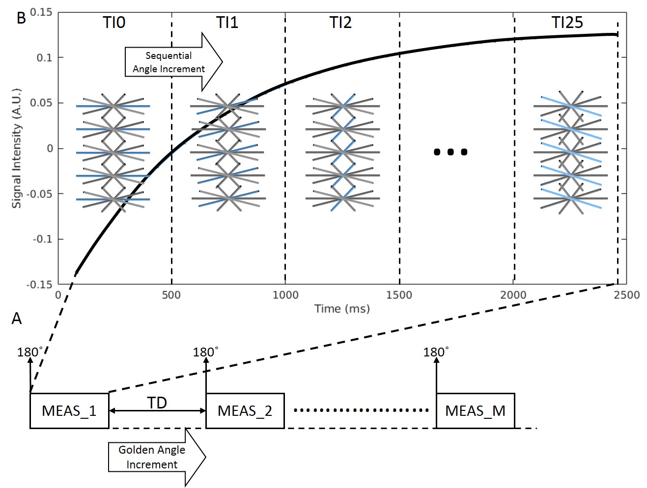
The 3D IR-radFLASH pulse sequence was implemented on a Siemens 3T Skyra scanner. Figure 1 shows a diagram of the sequence. It starts with an 180˚ slab-selective adiabatic inversion RF pulse, followed by data collection using a train of constant FA RF pulses and a radial trajectory with sequential view ordering in a k-z partition-first acquisition order. During the recovery period of each IR pulse, we acquire data for 25 TI groups. On each group we acquire one view/partition with the same angular orientation for all views; between groups the angular orientation of views is incremented sequentially. To complete the acquisition of all views in the group we re-invert the spins after a time delay (TD) to allow for recovery. The number of inversion periods, or measurements, M=13 yielded 13 views/partition. Since the number of views/partition is highly undersmapled we use the model-based algorithm from [6] for reconstruction of TI images from which the T1 maps are derived. Since each view within a group is associated with a different TI, the group is approximated to the average of the acquired TIs. The reconstruction algorithm was implemented on 8 Nvidia Tesla P100 GPUs using C++ with OpenCL.
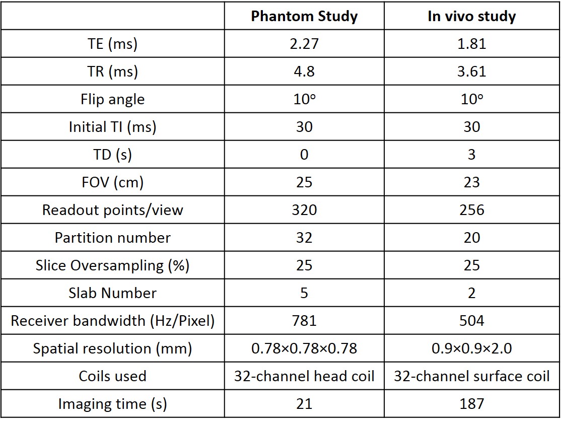
3D IR-radFLASH data for a phantom and in vivo studies were acquired using the parameters listed in Table 1. A slab-selective inversion pulse with a TD of 3s was used to allow for spin recovery and avoid slab cross-talk.
For comparison, 3D VFA T1 mapping data were acquired with a Cartesian spoiled gradient-echo pulse sequence with FA={2˚,5˚,9˚}, TE=1.66ms, TR=4.57ms, FOV=23cm, receiver bandwidth=400Hz/Pixel, spatial resolution=1.60×1.44×4.36mm. A low resolution B1 map was acquired for FA correction. Total scan time was 49s.
Results and discussion
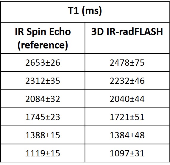
Table 2 shows T1 estimates for a NIST phantom. T1 values obtained with the 3D IR-radFLASH method are compared to reference values obtained using an IR spin-echo method. As the table shows, T1 estimates from the 3D IR-radFLASH matches the spin echo reference.
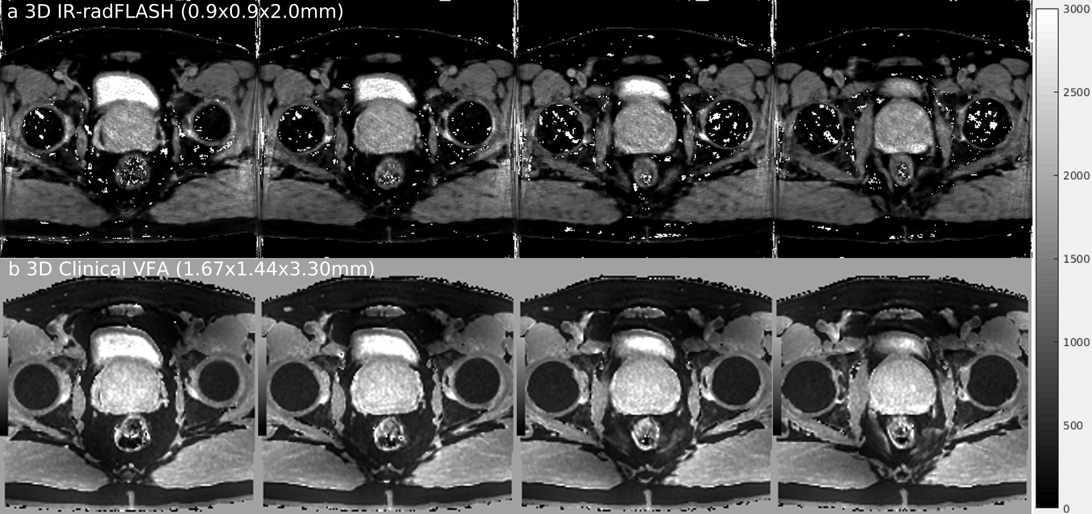
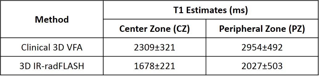
Figure 2 shows in vivo pelvic T1 maps for 4 out of 40 slices acquired with (a) the 3D IR-radFLASH and (b) the 3D VFA methods. In both cases the prostate’s center zone (CZ) and peripheral zone (PZ) can be identified. Table 3 shows the T1 values from these two zones for both methods. The VFA method overestimates T1, while the 3D IR-radFLASH method yields T1s consistent with those reported in the literature using a variable TR (VTR) method [4]. In [4] the authors showed that the VTR method provides stable and accurate T1 values compared to the VFA method. The drawback of the VTR method is the long scan time (~10 minutes) needed for data acquisition.
Conclusion
A B1 insensitive, 3D technique based on an IR radial FLASH technique combined with a model-based reconstruction was demonstrated for T1 mapping of the prostate. T1 maps with high spatial resolutions and high SNR can be acquired within a clinically viable time. The proposed method is a significant improvement over existing VFA T1 mapping methods used in the clinic.Acknowledgements
The authors would like to acknowledge support from the Arizona Biomedical Research Commission (Grant ADHS14-082996) and the Technology and Research Initiative Fund (TRIF) Improving Health Initiative.References
[1] Steinhoff S, Zaitsev M, Zilles K, Shah NJ. Fast T1 mapping with volume coverage. Magn Reson Med. 2001;46:131-140.
[2] Deichmann R. Fast high-resolution T1 mapping of the human brain. Magn Reson Med. 2005;54:20-27.
[3] Li W, Griswold M, Yu X. Rapid T1 mapping of mouse myocardium with saturation recovery Look-Locker method. Magn Reson Med. 2010;64:1296-1303.
[4] Fennessy MF, Fedorov A, Gupta NS, Schmidt JE, Tempany MC, Mulkern VR. Practical considerations in T1 mapping of prostate for dynamic contrast enhancement pharmacokinetic analyses. Magnetic Resonance Imaging. 2012;30:1224-1233.
[5] W. Liu, B Turkbey, J. Senegas, S. Remmele, C. Stehning, D. Daar, Y. Pang, M. Bernardo, and P. Choyke. Comparison of Look-Locker and Variable Flip Angle T1 mapping for DCE-MRI in Prostate Patients at 3T. In: ISMRM; 2010; Stockholm, Sweden.
[6] Li Z, Bilign A, Martin RD, and Altbach IA. Rapid high-resolution 3D T1 mapping using a highly accelerated radial inversion-recovery FLASH technique. In: ISMRM; 2017; Honolulu, Hi, USA.
Figures