4434
Design of a passive feed network to increase the transmit efficiency of dipoles at 7 Tesla1Radiology Department, C.J. Gorter Center for High Field MRI, Leiden University Medical Center, Leiden, Netherlands
Synopsis
In this abstract, we presented a new way of feeding a dipole type antenna which increases the transmit efficiency (B1+ per square root maximum SAR). The main radiating antenna element was printed on one side of a dielectric substrate with capacitive coupling to a shorter straight dipole element used as the feed element printed on the opposite side. Indirectly (passively) and directly fed (conventional) meander antennas were fabricated and their performances were compared numerically and experimentally. The indirectly fed dipole antenna exhibited increase in transmit efficiency for straight and meandered dipoles.
Introduction
Dipoles have been shown both theoretically1and experimentally2 to be efficient transmit elements for body imaging at high fields, defined as 7 Tesla and above. Introducing meanders into the dipole geometry has been demonstrated to be an efficient method for increasing the transmit efficiency (the B1+ per square root maximum SAR) compared to a straight line dipole. In this work we propose and evaluate a new 'indirect' feeding mechanism which further increases the transmit efficiency of a generalized dipole geometry, i.e. straight, meandered or other configuration. The main radiating antenna element was printed on one side of a dielectric substrate with capacitive coupling to a shorter straight dipole element used as the feed element printed on the opposite side. The performances of the indirectly fed meander dipole were compared with the conventional meander dipole with direct feed in electromagnetic simulations, phantom scanning, and thermal measurements.Methods
Electromagnetic simulations were performed in CST Microwave Studio 2016 (CST Studio Suite, Computer Simulation Technology, Darmstadt, Germany). Dielectric properties of the phantom used in both simulations and measurements were ɛr=80 and σ=0.4 S/m. Simulations of 10g averaged SAR and B1+ performances of passively'indirectly fed dipole antennas with different length of a feeding dipole element were performed. Two meander dipole antennas were fabricated – one with a passive indirect feed (Fig. 1) and the other with direct feed. The antennas were 28 cm long with two meanders placed 4.5 and 10 cm from the feed and fabricated on an FR4 substrate (ɛr =4.3, tanδ=0.025, substrate thickness was 1.5 mm). B1+ measurements were performed on a 7T scanner (Achieva, Philips Healthcare, Best, The Netherlands) using the DREAM sequence3. Thermal measurements using the proton reference frequency method4 were performed with both antennas on a rectangular PVP phantom with dielectric properties ɛr= 40 and σ = 0.75 S/m.Results
Figure 2 shows simulated B1+ normalized to the max SAR10g for a 90 mm and 110 mm feeding dipole lengths of indirectly fed antenna. Calculated B1+ efficiency (normalized to the max SAR10g) shows advantage of using an indirect feed mechanism over directly fed antenna for a given feeding dipole lengths. Figure 3 shows simulated and measured B1+ profiles (normalized to 1W of input power) of directly and indireclty fed meander dipole antennas. The length of the feeding dipole for the fabricated indirectly fed meander antenna was 110 mm. The profile of the B1+ normalized to the 1 W of input power was slightly higher for directly fed antenna compared to the indirectly fed dipole. There is good agreement between the simulated and acquired B1+ maps. Figure 4 shows results of MRI thermal measurements performed for the same input power and the same heating time. For the same input power, the indirectly fed antenna produced 50% lower temperature than directly fed antenna. Figure 5 shows B1+ efficiency calculated for measured temperature. Around 10% higher efficiency has been achieved with fabricated indirectly fed meander dipole.Discussion
From Fig. 2 we conclude that max SAR10g decreases by decreasing a length of a feeding dipole in indirectly fed antenna. At the same time, B1+ per square root of input power also decreases with decreasing the feeding dipole length, however, B1+ efficiency calculated for max SAR10g was higher than directly fed meander for both simulated indirectly fed antennas. Thermal measurements also showed 50% higher temperature profile of directly compared to indirectly fed antenna (feeding dipole length was 110 mm).Conclusions
We proposed a simple way of lowering SAR of the single dipole element. The proposed method is valid for all dipole type antennas (not shown here). The passive indirect feeding mechanism shows a lowering of SAR when used with other dipole antenna designs including a short straight dipole, snake dipole, inter-segmented dipole, etc.Acknowledgements
This work was funded by the ERC NOMA-MRI, grant number 670629.References
1. Lattanzi R, Sodickson DK. Ideal current patterns yielding optimal SNR and SAR in magnetic resonance imaging: computational methods and physical insights. Magn Reson Med 2012;68(1):286-304.2. Raaijmakers AJ, Italiaander M, Voogt IJ et al. The fractionated dipole antenna: a new antenna for body imaging at 7T. Magn Reson Med 2016; 75:1366-1374.
3. Nehrke K, Börnert P. DREAM—a novel approach for robust, ultrafast, multislice B1 mapping. Magn Reson Med 2012; 68: 1517–1526.
4. Yuan J, Mei C-S, Panych LP, McDannold NJ, Madore B. Towards fast and accurate temperature mapping with proton resonance frequency-based MR thermometry. Quant Imaging Med Surg. 2012;2(1):21-32.
Figures
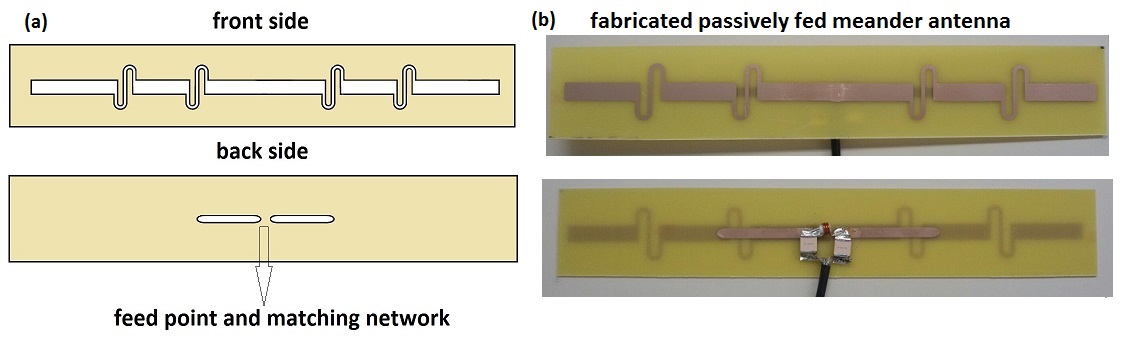
Figure 1. Geometry (a) and photo (b) of the fabricated passively fed meander dipole antenna. Meander dipole antenna designed for operation at 300 MHz was printed on one side of substrate, while on the opposite side short dipole with a matching circuit and feeding connection were placed.
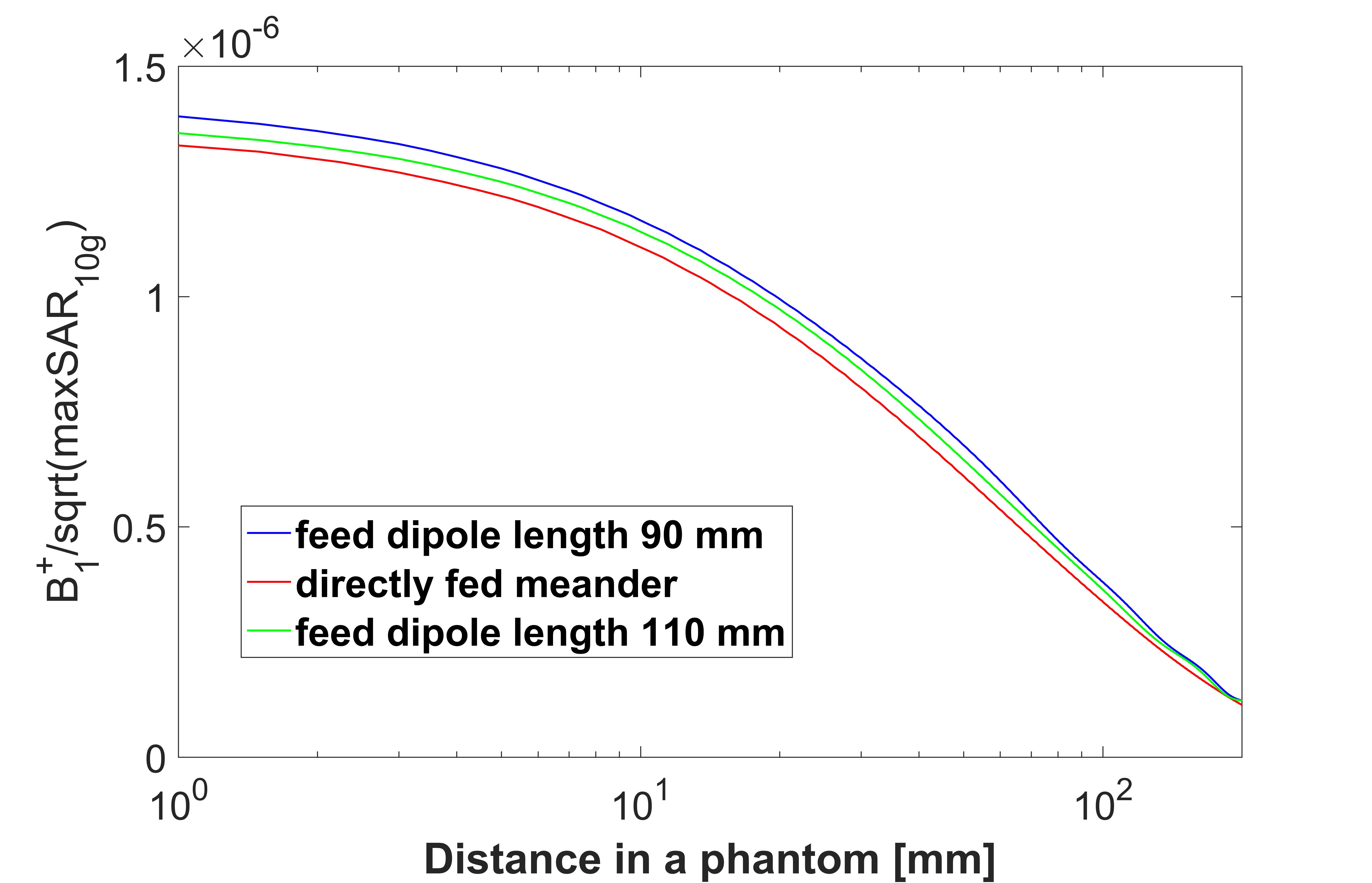
Figure 2. Simulated B1+ efficiency divided by square root of max SAR10g for passively fed meander dipole antennas with 90 mm and 110 mm length of the feeding dipole.
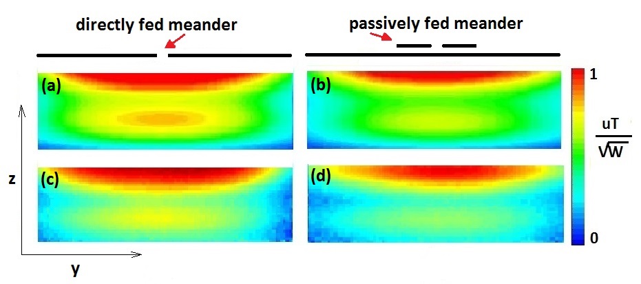
Figure 3. Simulated ((a) and (b)) and measured ((c) and (d)) B1+ profile on a phantom for directly fed ((a),(c)) and passively fed ((b),(d)) meander dipole antenna. The passive antenna feeding dipole length was 110 mm. The phantom depth was 85 mm which is the likely cause of the observed interference pattern in the B1+ field observed in both simulation and measurements.
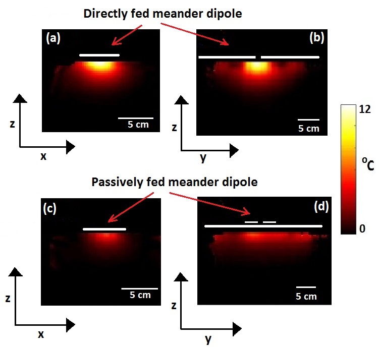
Figure 4. Thermal maps of directly ((a),(b))and passively fed ((c), (d)) meander dipoles. (a) and (c) are central transversal while (b) and (d) are central sagittal slices. The temperature produced by passively fed dipole was 50% lower than the temperature produced by directly fed dipole for the same input power.
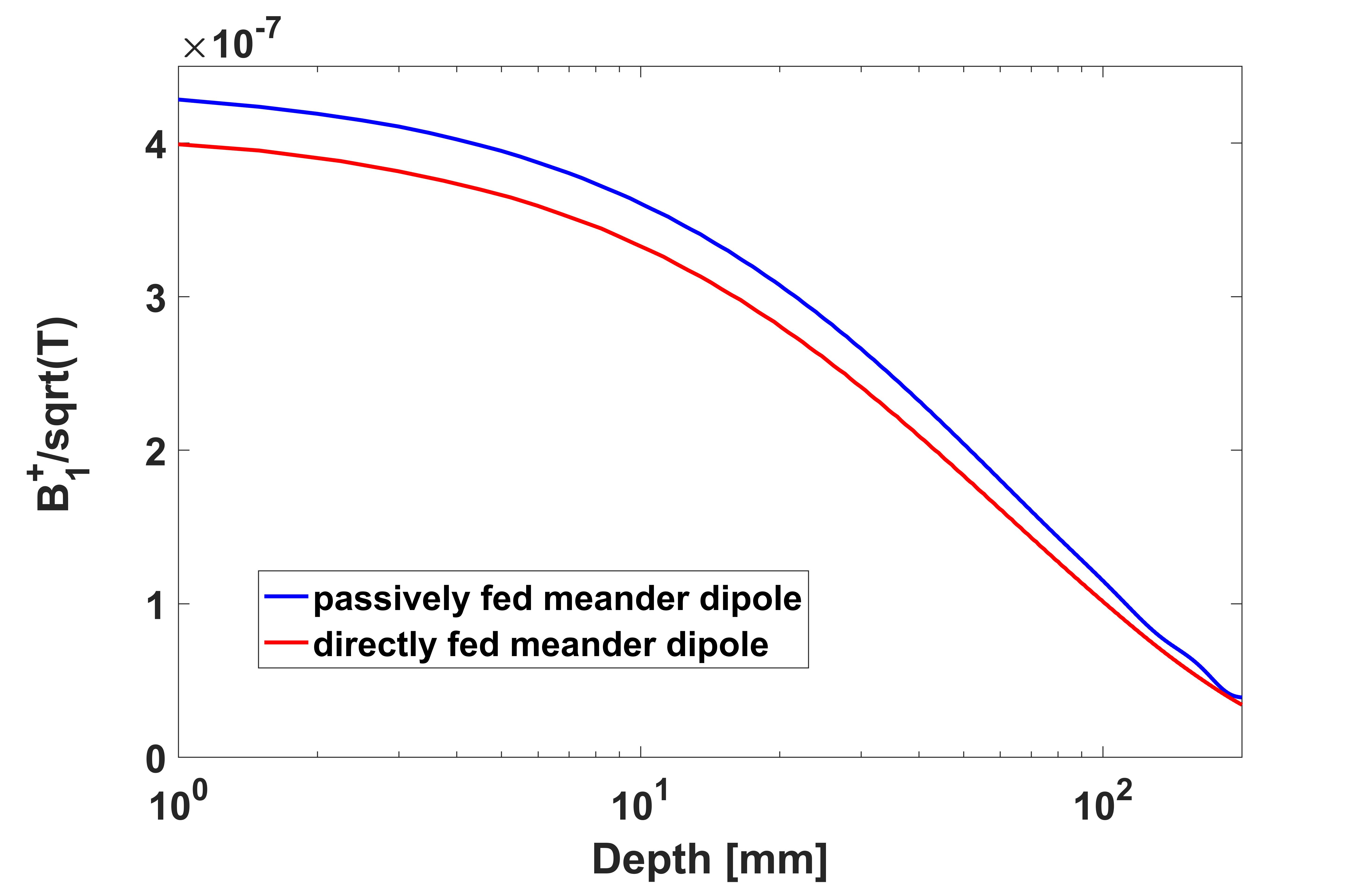
Figure 5. B1+ field normalized per square root of measured temperature for directly and passively fed meander dipole antenna.