4433
Optimizing the combination of preamplifier input impedance and coil impedance for high-density receive arrays1University of Western Ontario, London, ON, Canada
Synopsis
Low-profile preamplifiers were developed to be used in multichannel coil arrays. Optimizing the combination of preamplifier input impedance and coil impedance for high-density receive arrays indicates that the highest SNR is obtained when using high input-impedance preamplifiers connected directly to high-impedance coils.
Introduction:
Increasing the static magnetic field strength of an MRI scanner can improve the signal-to-noise ratio (SNR), image contrast, and spectral resolution in certain applications. Ultra-high field 7T MRI scanners for human use have over double the SNR of clinical 3T instruments and offer potential for better lesion conspicuity, faster image acquisition to reduce motion artefacts, and earlier disease detection at the submillimeter scale [1-4]. At 7 T, the frequency of operation is raised to 297 MHz. The higher frequency increases inter-coil coupling, as well as the sensitivity of the coil to asymmetric stray capacitances at the preamplifier input that are responsible for common-mode signals and sheath currents that cause unwanted feedback to the loop antenna and potentially self-oscillation of the antenna-preamplifier subsystem. Thus, a custom-designed, low-noise amplifier is one of the important elements in the receiver to amplify the signal and to improve the SNR. In this work, small-footprint, low-noise preamplifiers are developed to meet the space requirements of high-density, multichannel coil arrays. An SNR comparison is conducted to determine the optimal combination of preamplifier input impedance and coil impedance.Methods:
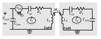
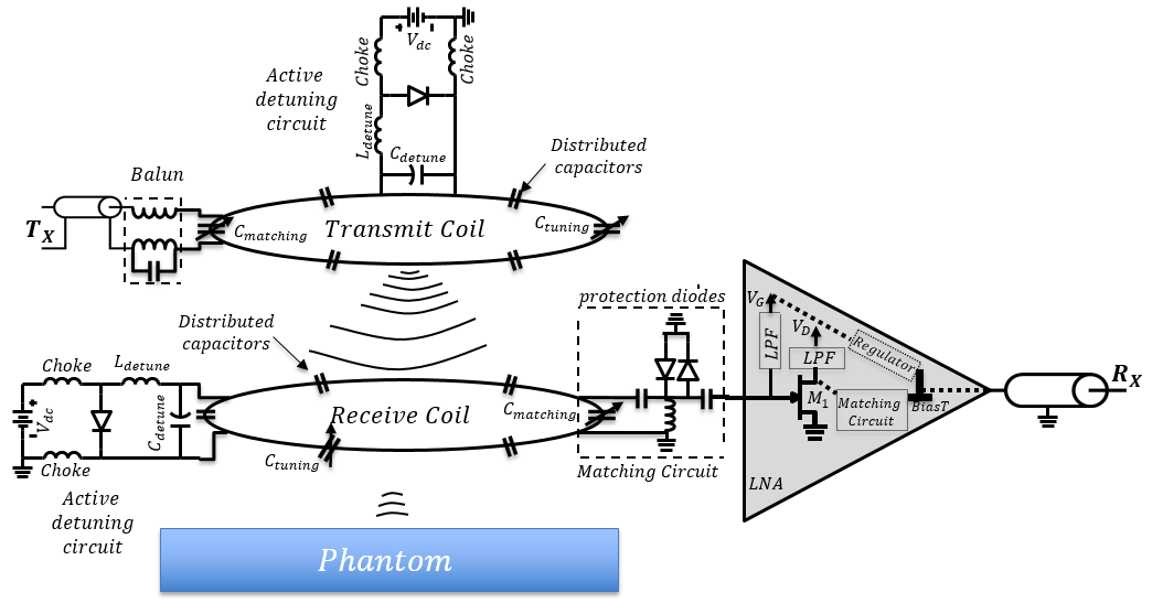
The noise figure of a receiver strongly depends on the first stage, the noise figure of subsequent devices will be divided by the gain of the previous stages and become less important in practice; therefore, the noise figure of the MRI receiver chain can be minimized by designing a very low noise preamplifier. Since the transistor performance determines the overall performance, a GaAs enhancement-mode pseudomorphic high electron mobility transistor (ePHEMT) should be utilized in the first stage of the preamplifier. To achieve the lowest noise figure, Fmin, the reflection coefficient of the source (Γs) should be as close as possible to the optimum reflection coefficient (Γopt) required by the transistor. In this case, the second term of the equation tends to zero, and the minimum noise figure can be obtained: NF=Fmin+(4Rn / Z0)(abs(Γs-Γopt)2 / ((abs(1+Γopt)2abs(1-Γs)2), where 4Rn / Z0 is the normalized noise resistance. Typically, an impedance much higher than 50 Ω is required for FETs to produce high Γopt and a low Fmin. In addition, both the high impedance of the coil and the high input impedance of the preamplifier will serve to reduce the current flowing in the coil; therefore, for multichannel receive arrays, the coupling between coils is reduced. ADS simulations were performed to determine the noise circles versus available gain and find out the Γopt required by the transistor. In addition to geometric decoupling [4], M12 can also be minimized by using high-impedance coils in conjunction with high-input-impedance preamplifiers, thereby limiting I2: Vout = Vsig+(R1+j(ωL1-1/ωC1t))I1+jωM12I2 (Fig. 1). SNR was measured on the scanner for 50 Ω and 500 Ω input-impedance preamplifiers in conjunction with a receive coil tuned to either 5 Ω, 50 Ω, or 500 Ω. The experimental setup is shown in Fig. 2.
Results:
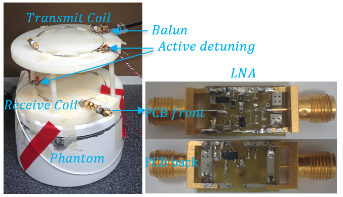
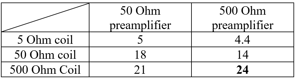
To reduce the size of the preamplifiers to 1.5cm×1cm, single-stage preamplifiers, with low noise figure and two-layer PCB fabrication, were implemented. The small size allows the preamplifiers to be mounted directly on receive coils in high-density arrays where space is at a premium. This also reduces cable coupling and losses that exist between coils and preamplifiers. In the preamplifier, an ATF34143 transistor was used. This transistor has a very low Fmin of 0.2 dB. By choosing the proper source impedance (Zs), Γs tends toward Γopt, and therefore the minimum noise figure can be obtained. Form the noise circle simulation performed in ADS, optimum source impedance determined to be 592+j288 Ω with less than 0.1 dB added noise to Fmin while the gain was above 22 dB. Therefore, the coil should be tuned and matched to the Zs that provides the best noise performance. Table 1 presents the experimental SNR comparison of 50 Ω and 500 Ω input-impedance preamplifiers connected directly to coils matched to 5 Ω, 50 Ω, or 500 Ω. The results show that the 500 Ω coil connected to a 500 Ω input-impedance preamplifier had higher SNR than all other combinations of preamplifier input impedance and coil impedance.Conclusions:
In this work, low-profile preamplifiers were developed to be used in multichannel coil arrays. The results of this study indicate the highest SNR is obtained when using high input-impedance preamplifiers connected directly to high-impedance coils.Acknowledgements
The authors received financial supports from NSERC Canada, the Ontario Research Fund (ORF) and CMC Microsystems.References
- C. L. Lim, P. Serano and J. L. Ackerman, “Pre-amplifiers for a 15-Tesla magnetic resonance imager,” RF and Microwave Conference (RFM), 2013 IEEE International, Penang, 2013, pp. 295-299.doi: 10.1109/RFM.2013.6757270.
- K. M. Huber, M. Hemmerlein, S. Biber, R. Oppelt, and K. Wicklow, “A Preamplifier for 7T MRI with Extended Dynamic Range and Integrated Cable Trap”, Proc. Intl. Soc. Mag. Reson. Med. 16, 2008.
- A. Reykowski, S. M. Wright, and J. R. Porter, “Design of Matching Networks for Low Noise Preamplifiers”, Magn. 1995.
- P. B. Roemer, W. A. Edelstein, C. E. Hayes, S. P. Souza, and O. M. Mueller, “The NMR phased array”. Magn Reson Med, 16: 192–225, 1990.
Figures