4432
Optimal Bazooka Balun Proportions1GE Healthcare Coils, Aurora, OH, United States
Synopsis
In MRI, traditional RF coils have cables, which supply the on-coil electronics with power and carry the received signals out from the receive elements to further amplification, digitization and post-processing. The standard technique for blocking currents being induced on the cables uses RF traps, colloquially called bazooka baluns, which represent parallel resonant tanks coupled (magnetically) to the cable. Question: If the volume of the bazooka balun is fixed, what would be its diameter and length so that the impedance of the balun is maximized?
Purpose
Cables in a RF environment in MRI are usually populated with multiple bazooka baluns, which function as parallel resonant tanks. The goal is to generate high cable sheath impedance at the frequency of interest, so that the induced current is minimized. Parasitic currents on cables cause B1 distortion (both in Tx and Rx phases), local SAR increase and unwanted coupling with other resonant systems, e.g. system body coil. A cable becomes bulky and heavy with the addition of baluns; so, obvious problems arise: given a cylindrical bazooka balun for a given volume what is a maximum impedance generated on the cable?Theory
A Classical Bazooka Balun is defined as coaxial structure coupled with the cable. Its impedance on the cable, when tuned to frequency $$$\omega_0/(2 \pi)$$$, achieves maximum value $$$Z_{max}=\omega_0^2 M^2/R$$$ [1] , where $$$M$$$ is mutual inductance between the balun and the cable and $$$R$$$ is the series resistance of the balun.
Considering the bazooka balun with the length $$$l$$$, inner and outer radii $$$a$$$ and $$$b$$$ respectively and neglecting wavelength effects, mutual inductance between the balun and the cable can be calculated as an integral of the magnetic energy density over the volume of the balun resulting in $$$M=\mu_0/(2\pi) l \ln(b/a)$$$.
Resistance of the balun needs to account for losses in the conductor and dielectrics comprising the balun. In this exercise, we will neglect dielectric loss, concentrating only on metallic resistance. Again, neglecting wavelength effects, and considering that the current flows along the balun’s length and radially on its ends the resistance of the balun is
$$R_{conductor}=\frac{1}{\sigma} \frac{1}{2 \pi \delta}\left(\frac{l}{a}+\frac{l}{b}+2\ln\frac{b}{a}\right)\tag{1}$$
where $$$\sigma$$$ is conductor’s conductivity, $$$\beta=\sqrt{2/(\mu_0 \omega_0 \sigma)}$$$ skin depth at frequency $$$\omega_0/(2\pi)$$$.
The volume of a bazooka balun is $$$V=\pi l a^2 (k^2-1)$$$, where $$$k=b/a$$$. Fixating the volume and the inner radius (which is constrained by the cable outer radius), we can find a relationship between the length of the balun and its outer radius $$$l=c_g/(k^2-1)$$$ where $$$c_g=V/(\pi a^2)$$$.
Replacing mutual inductance and resistance in the equation for maximum impedance we obtain
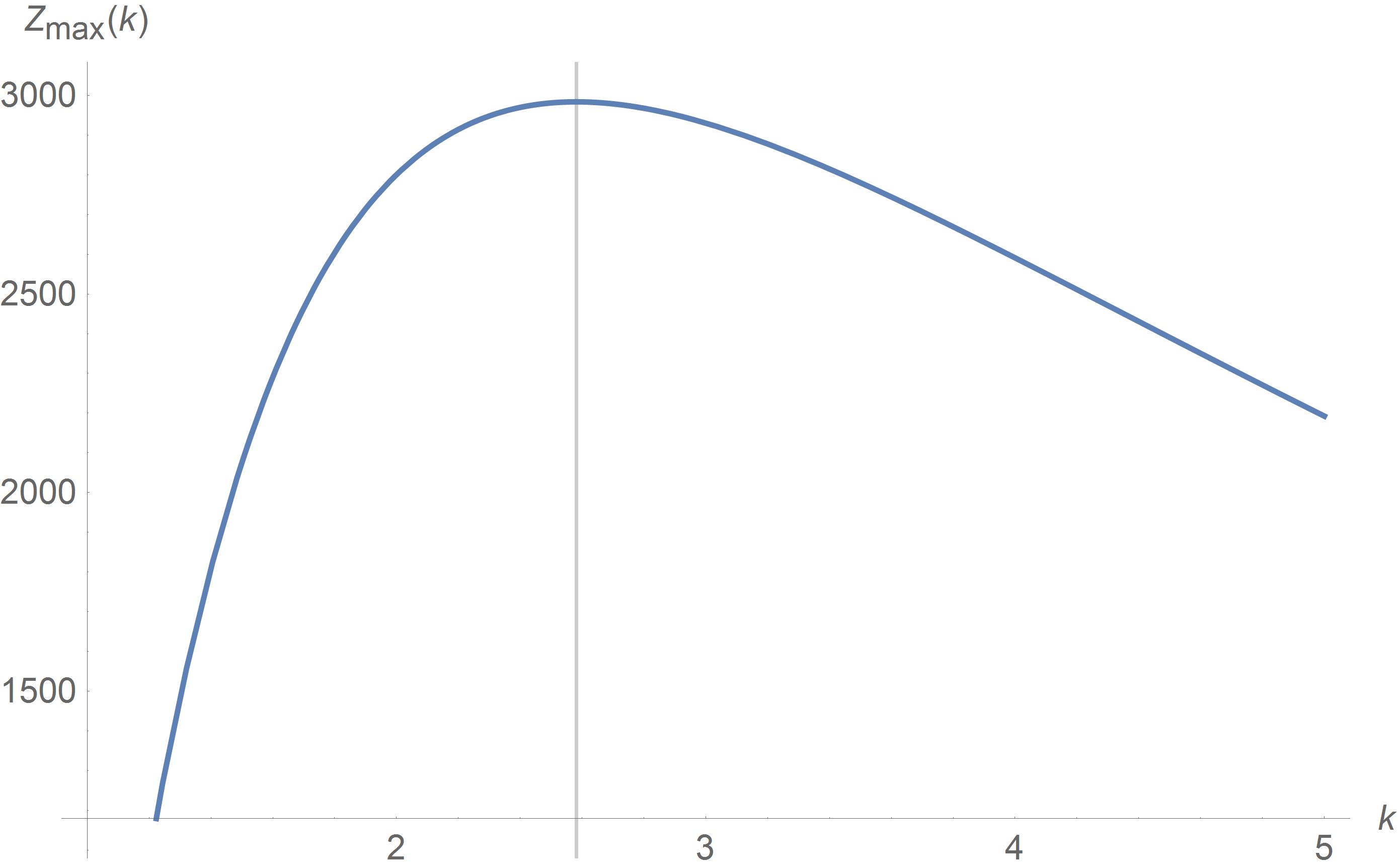
$$Z_{max}=2\pi\delta\sigma\omega_0^2 \left(\frac{\mu_0}{2 \pi}\right)^2 \frac{a c_g^2\left(\frac{\ln k}{k^2-1}\right)^2}{\frac{c_g}{k^2-1}\left(1+\frac{1}{k}\right)+2\ln k}\tag{2} $$ .
If for a given balun’s volume we plot the maximum achievable impedance (2) as a function of parameter $$$k$$$ we obtain the dependence in Figure 1.
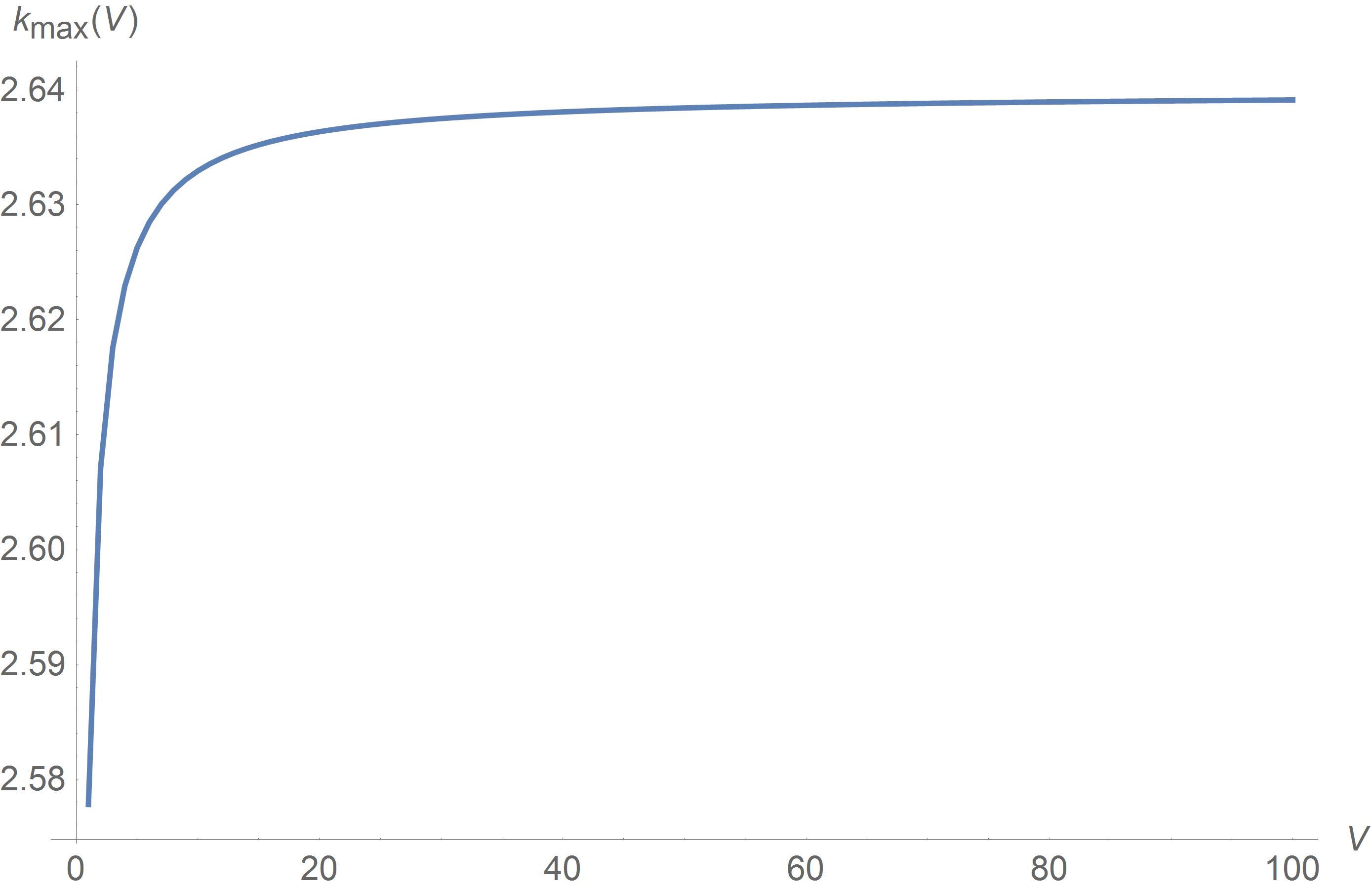
The ratio in figure 1 is calculated for V=1 ml. If we try to find the k values for more volumes we will get Figure 2.
Simulations Results
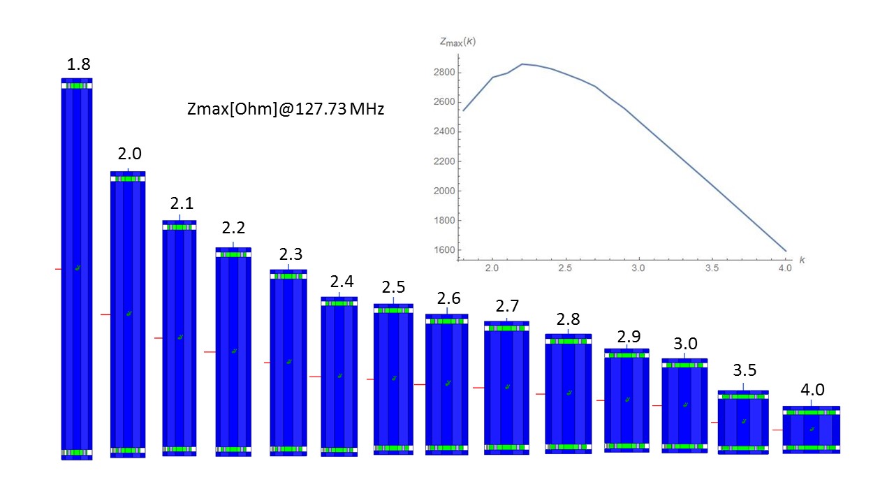
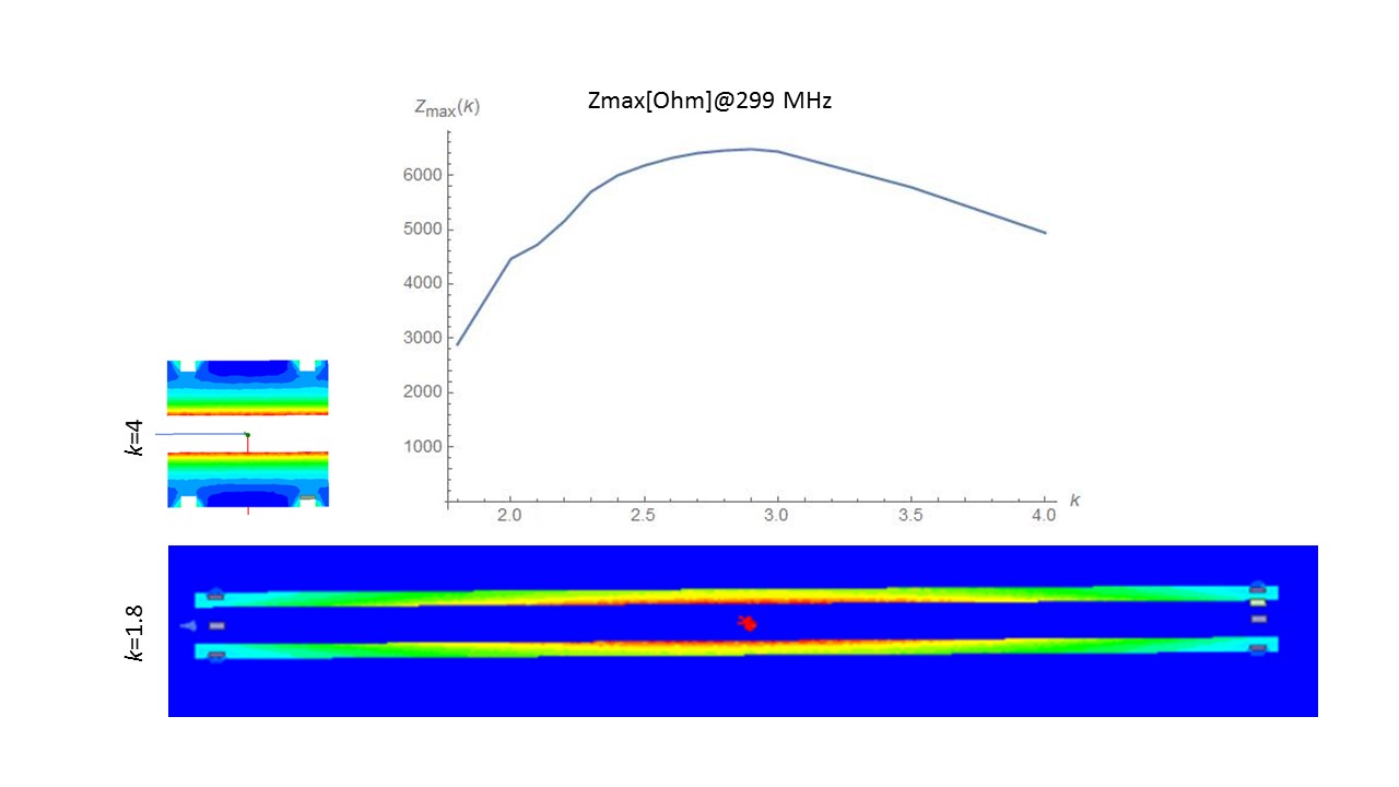
When considering wavelength effect and the losses of the dielectric, FEM simulation is the tool of choice for a parametric study like this. For example, we created a parametric model of the balun with volume 50 ml which was tuned to resonate at the 127.73 MHz (Figure 3). For each form factor k the balun was tuned to the resonance frequency by adjusting capacitance distributed on both ends of the balun. The simulation graph shows that there is a kmax factor for which impedance of the balun is maximized. It is remarkable that the simulation result is similar to the analytical result (Figure.1) where only the resistance of the conductor was taken into account and wavelength effects were neglected. A similar simulation study has been done for 299 MHz, where, due to a shorter wavelength, the balun’s performance is affected – and in turn the optimal shape (Figure 4). The much shorter wavelength (especially inside the balun’s dielectric material) is a cause of considerable magnetic field variation along the baluns’s length, which leads to lower inductance. To achieve the maximum impedance at high frequencies baluns need to be wider than their low frequencies counterparts with same volumes.
Conclusions
From both the analytical and simulation results, there is a clear indication that when the balun’s volume is fixed a cylindrical bazooka balun achieves a maximal impedance for a certain form factor. The analytical model can show the nature of this optimal proportion; however, for an actual balun including the capacitors' losses, its dielectric filling and its housing, the best method to search for its optimum shape is through simulations. For high field MRI where wavelength is comparable with the length of the balun, best proportions indicate a shorter but wider balun. When the weight or volume of the total cable assembly is desired to be minimized, we can utilize this technique to maximize the total impedance of the assembly. We can also restate the problems inversely: given the required impedance per unit length of cable we can calculate its impact on baluns dimensions, overall mass and number of baluns required for certain situations.Acknowledgements
No acknowledgement found.References
1. L.D. Landau, L.P Pitaevskii, E.M. Lifshits, Electrodynamics of Continuous Media, 2nd Edition: Volume 8, § 62Figures