4430
A Signal Loss Compensation Method in an RF switch matrix system in Ultra High Field MRI1Institute of Neuroscience and Medicine - 4, Juelich, Germany
Synopsis
A crossbar switch matrix can be flexibly connected to any input and output paths via RF switches. However, this type of matrix creates open-stubs in the RF lines. Since the RF wavelength becomes shorter as the magnetic field increases, signal loss due to impedance variations in RF pathways becomes severe, thus degrading image quality. In this study, we propose an advanced compensation method and verify its performance in ultra-high field MRI with single and multi-channel array coils.
Purpose
RF receive channels are the path between the RF coil and the receivers on the MRI spectrometer. Ordinarily, the number of receive coil connectors and receive paths are different; however, recently the channels of receive coils have been increased to correspond to the number of receive paths, including analogue-to-digital converters (ADCs). Therefore, modern MRI scanners need, for example, a switch matrix to automatically connect receive coils with their appropriate receive paths. The most commonly used matrix structure is a crossbar type switch matrix,1 where a crossbar switch matrix can be flexibly connected to any input and output paths via RF switches. However, this type of matrix creates open-stubs in the RF lines. Since the RF wavelength becomes shorter as the magnetic field increases, signal loss due to impedance variations in RF pathways becomes severe, thus degrading image quality.2,3 In this study, we propose an advanced compensation method and verify its performance in ultra-high field MRI with single and multi-channel array coils.Methods
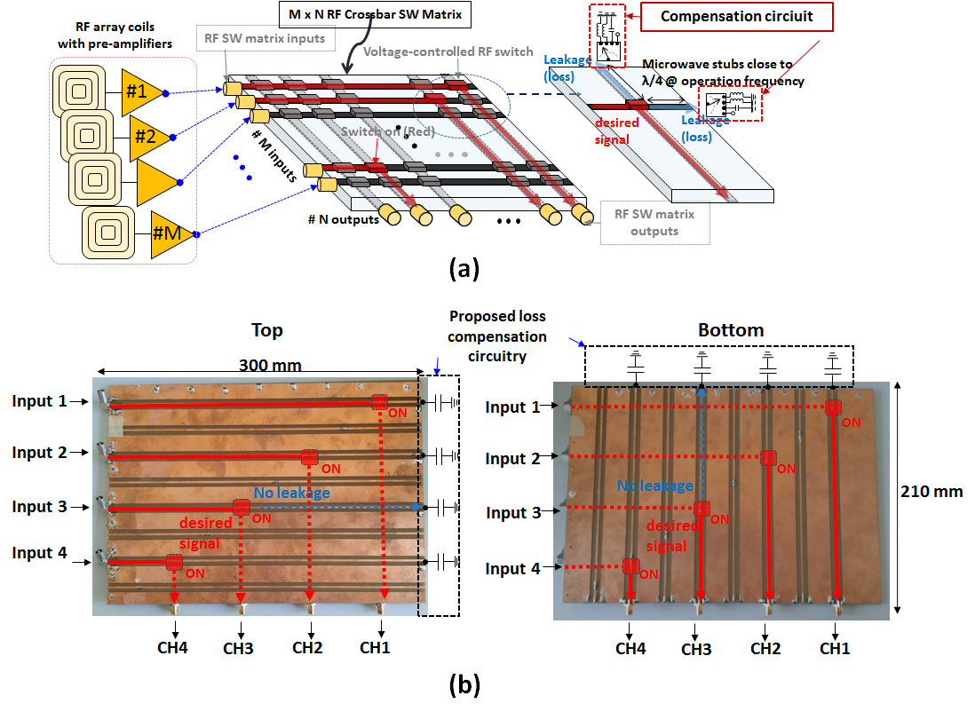
Fig. 1(a) shows a cross-bar-type switch matrix, including the compensation circuits on the edge of the RF signal path. To evaluate the effect of the open-stub and compensation circuit, a 4x4 switch matrix was constructed with a double-layer FR4 PCB. The dimensions of the matrix board were 300 mm × 210 mm as shown in Fig. 1(b). When the length of the open-stub is close to λ/4, and the signal loss is large, this compensation circuit switches to a specified capacitor value. In a previous study, the compensation circuitry was only present on the opposite side of the input stage.2,3 However, in ultra high-field MRI, the compensation circuitry is also required on the opposite side of the output, thus, as shown in Fig. 1(b), the compensation circuitry is located on both the opposite side of the input port and output port. To measure signal loss according to the stub length, the RF path loss was measured using a network analyser. MR images were acquired using an in-house assembled 9.4 T animal MRI scanner4 with a gradient echo sequence (TR = 40 ms, TE = 3.85 ms, averages = 2, acquisition time = 20 seconds, resolution = 100 µm x 100 µm, and slice thickness = 1 mm). To calculate the SNRs, noise images were separately acquired using the identical protocol with a zero transmit power. A home-built quadrature birdcage coil and a commercial 4ch Rx only coil (RAPID, Germany) were used to evaluate the switch matrixResults
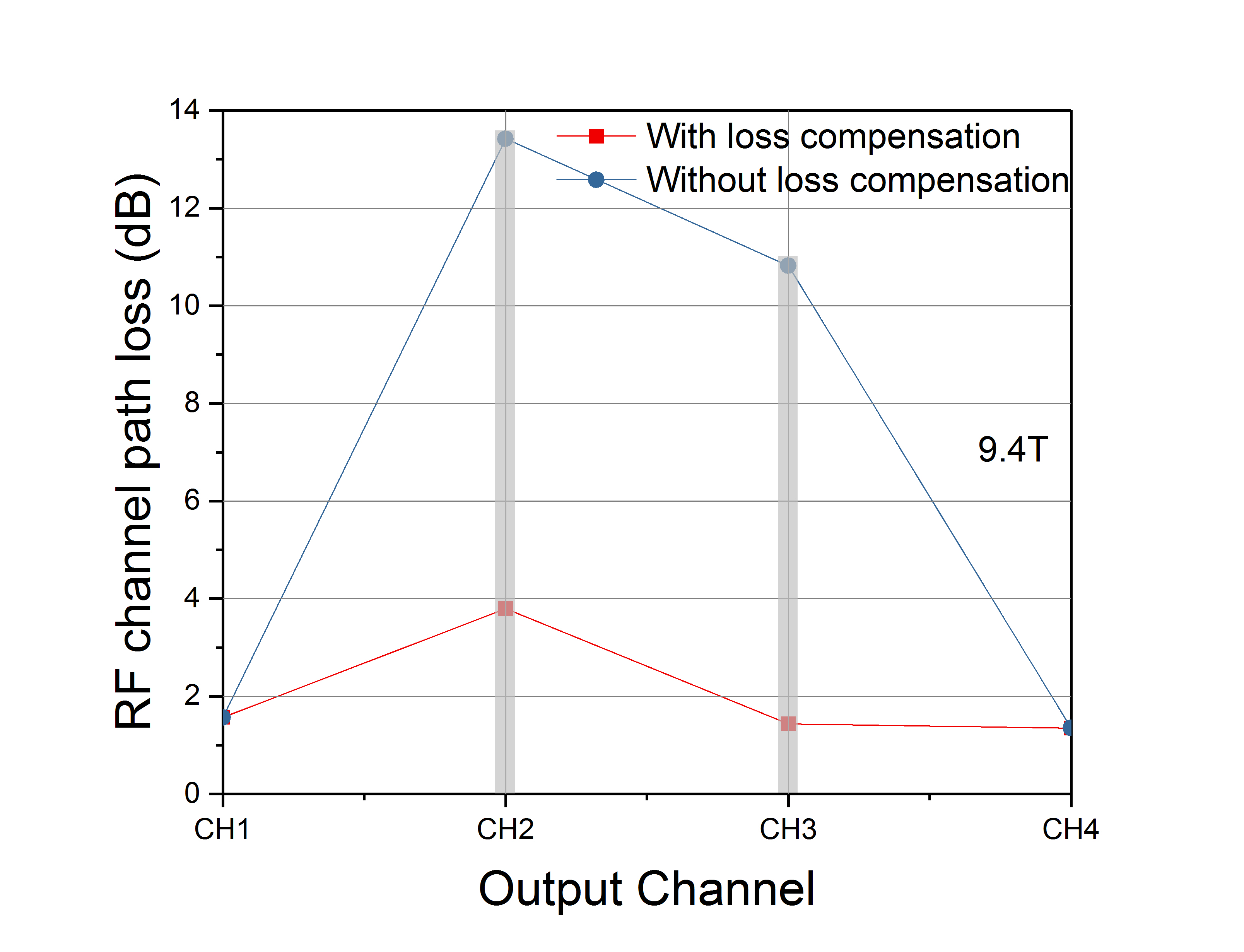
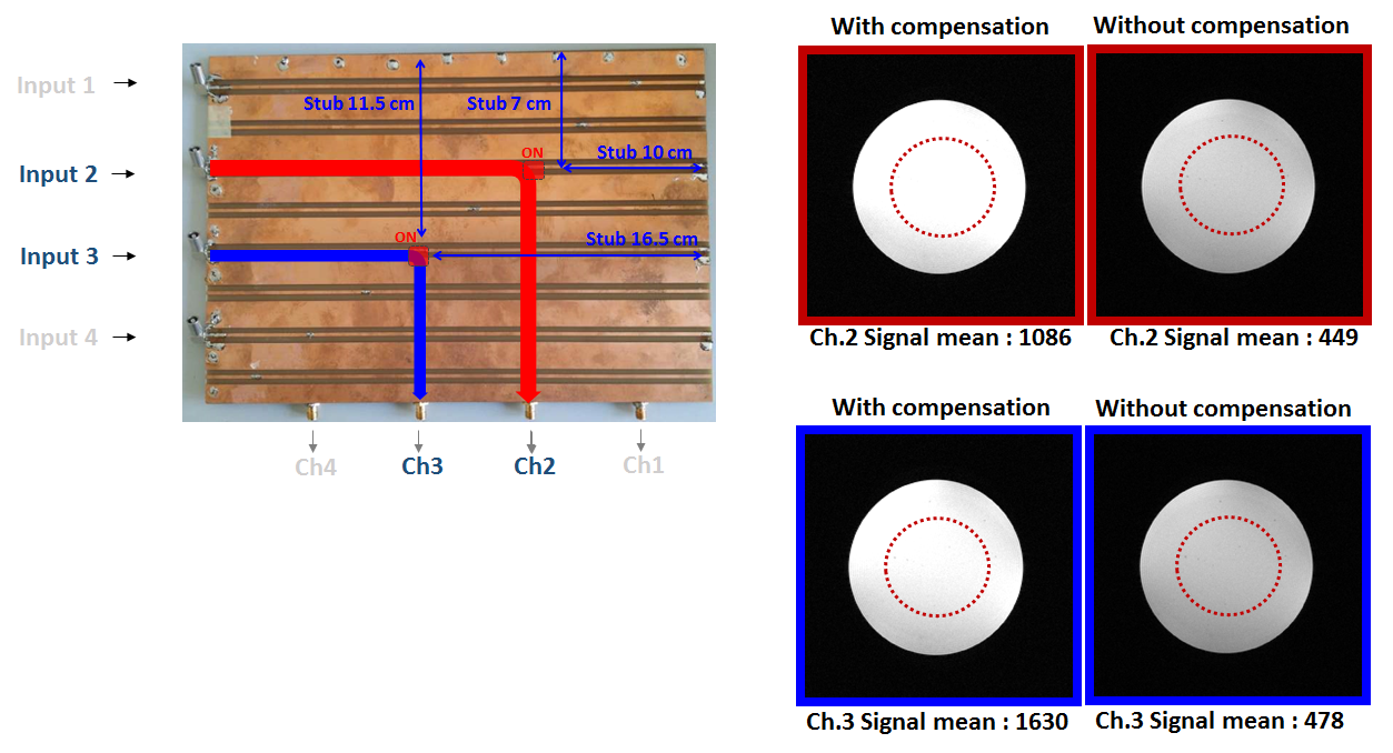
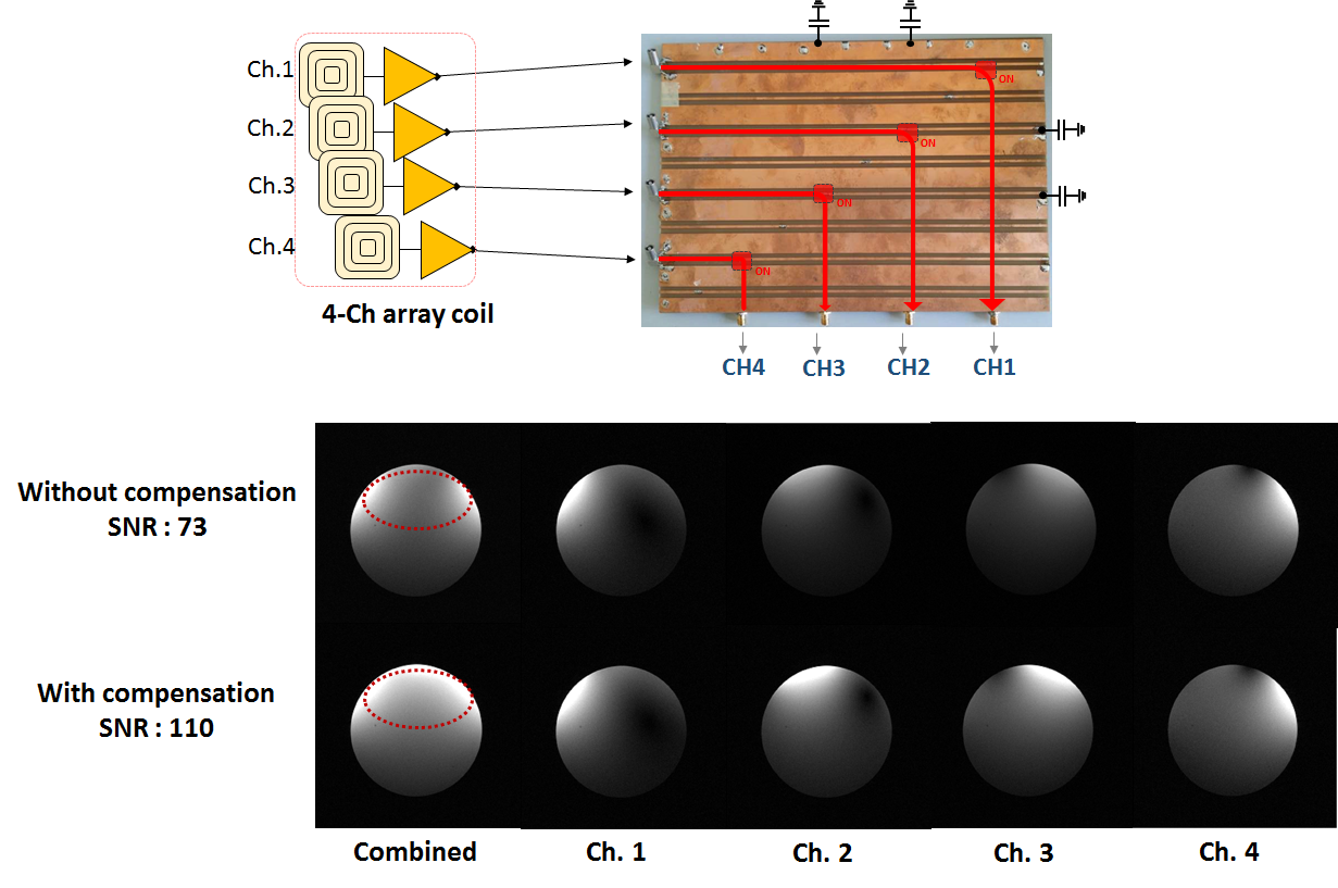
Fig. 2 shows the measured signal path loss of each channel of the switch matrix at 9.4 T, with and without the compensation capacitor (91 pF). Channel 1 was used as a reference. The open stub length of channels 2 and 3 were close to λ/4, and the signal losses were about 14 dB and 11 dB, respectively. By the application of compensation, the signal losses were significantly reduced. Phantom images acquired using a single-channel coil are shown in Fig. 3 and indicate a significant signal loss in channel 2 and channel 3. However, by using the compensation capacitors, the losses were minimised. As shown in Fig. 4, multi-channel images were acquired using a 4-channel Rx only coil. SNR was degraded by around 34% without compensation, compared to that of the reference. It was also shown that SNR was recovered using the compensation circuit.Discussion
We have demonstrated the performance of the proposed switch matrix using either a single-channel coil or multi-channel coils with an ultra-high field MRI scanner. Due to the shorter wavelength at ultra-high field, it was necessary to compensate the signal loss both in vertical and in horizontal paths, and we have confirmed that this compensation method is effective.Acknowledgements
No acknowledgement found.References
[1] Kröckel H. Switching matrix with two control inputs at each switching element. Google Patents; 2010.
[2] Lee H. Reconfigurable multi-channel RF crossbar switch matrix for MRI receiver front-end. Electron Lett. 2017;53(6):380-1.
[3] Ko Y-K, Lee HL, Choi C-H, Shah NJ. A technique to compensate signal loss in an RF switch matrix system in MRI. In Proceeding of the 25th Annual Meeting of ISMRM, Honolulu,USA; 2017.
[4] Choi C-H, Ha Y, Veeraiah P, Felder J, Möllenhoff K, Shah NJ. Design and implementation of a simple multinuclear MRI system for ultra high-field imaging of animals. J Magn Reson. 2016;273:28-32.
Figures