4428
Output Filter Design for Gradient Amplifier and Shimming Amplifier of MRI: an Overview1Department of Radiology, Medical Physics, Medical Center University of Freiburg, Faculty of Medicine, University of Freiburg, Freiburg, Germany
Synopsis
Switch-mode gradient amplifiers are widely employed in magnetic resonance imaging systems to drive gradient coils with high current and voltage to provide fast slew rates. The pulse-width modulation control results in unavoidable current ripple and switching noise. Therefore an effective filter is required to attenuate the current ripple and switching noise to avoid image artifacts. Common methods include using single or two stages of LC low pass filter with a disadvantage of bulky size and low ripple attenuation at the switching frequency. Here we present four different filters as alternative designs that introduce a notch mode.
Introduction
The pulse-width modulation of switch-mode gradient amplifiers results in current ripple and switching noise. To minimize the degradation of imaging quality, an effective filter is required. Coupled-inductor based ripple cancellation filter was proposed as an alternative to the conventional LC filter with better attenuation at the switching frequency 1. Another form of coupled-inductor filter commonly used in power converters could be adopted for gradient/shimming amplifiers 2-4. A further attractive option is uncoupled type LLC-LC filter 4, and also LC-LCC filter is an interesting option. This work provides reviews on the design of these different filters and compares them experimentally. The performance of filter prototypes is compared and discussed.Method
To balance the input ripple current of filter and slew rate of coil, a lower filter inductance is chosen compared with a relatively high inductance of a typical gradient coil and the filter effective attenuation is sacrificed for conventional clinical scanner applications. Fortunately, the inductance of each coil element is only about 11µH in our home-built matrix gradient coil 5. Therefore the input inductance of the filter is chosen to be close to the coil element inductance in this study. The filter circuit consists of two symmetrically equivalent identical single-ended filter circuits. To simplify the analysis, the block diagram of single-ended filter is shown in Fig. 1.
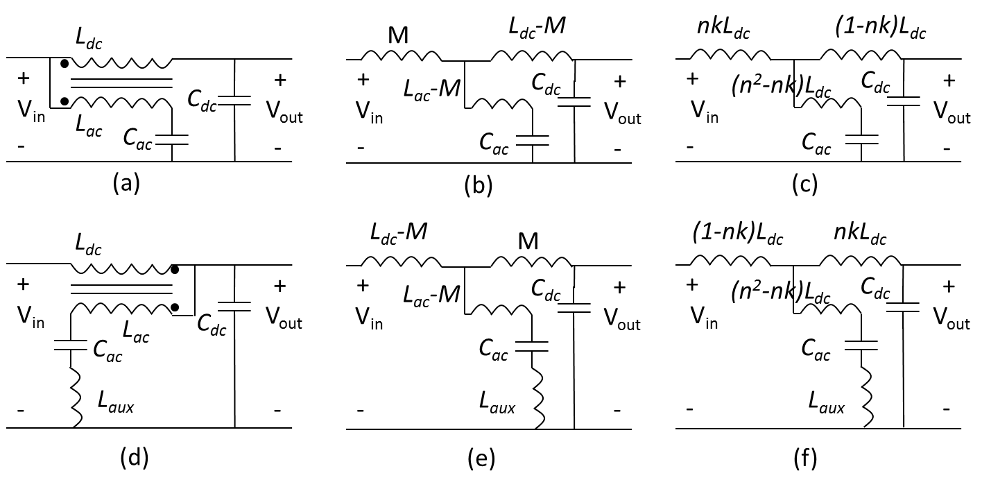
Coupled-inductor filter design: A coupled-inductor filter consists of one ferrite core, two coils, and two capacitors. Compared with 4th order cascaded LC filter, it has a lower number of magnetic components and a smaller size. A detailed description of the coupled-inductor filter (type-1) with T-equivalent-model and design procedure can be found in 2-4. A detailed description of another type of coupled-inductor filter (type-2) with a transformer-model can be found in 1. To understanding of the coupled-inductor filter operation, T-equivalent-model is preferred. The coupled-inductor filter and corresponding T-equivalent-model are presented in Fig. 2.
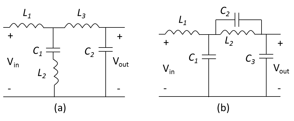
Uncoupled LLC-LC filter and LC-LCC filter design: The disadvantage of the coupled-inductor filter is that it is highly sensitive to the coupling coefficient. Uncoupled type filter LLC-LC filter is another attractive option when the filter size is not a constraint. Similarly, LC-LCC filter is an alternative uncoupled type filter where the parallel resonance is used to replace the series resonance circuit. Both uncoupled type filters are shown in Fig. 3.
Five different filters were implemented for 30V/20A shimming
amplifier with traditional PWM modulation. The switching frequency of amplifier
and the notching frequency of filter are 100 kHz and 100 kHz, respectively.
Bandwidth of the filter is set to slightly larger than 20 kHz. As a
reference, the conventional LC filter was also implemented with a very low
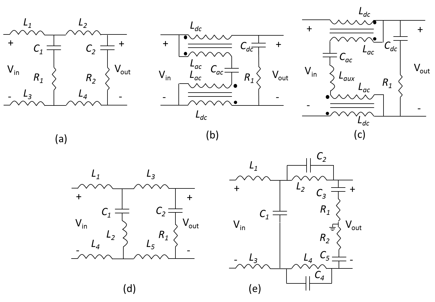
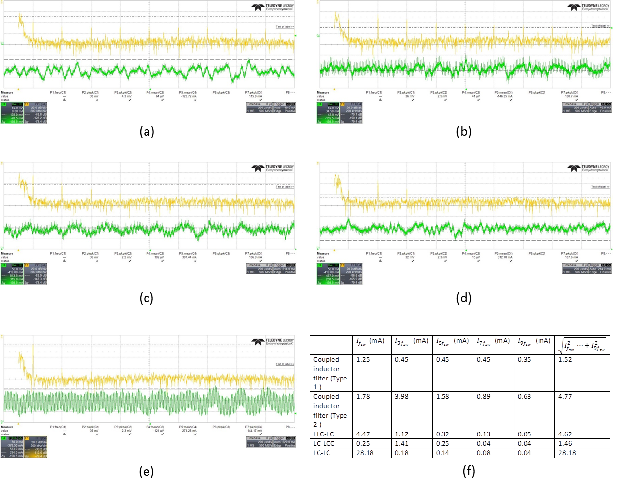
characteristic impedance. The schematics
and results of filters are shown in Fig. 4 and Fig. 5, respectively.
Results and Discussion
The coupled-inductor filters and uncoupled filters result in higher ripple attenuation than a conventional LC filter with the same LC values. The coupled-inductor filters also have a smaller size because of the two coupled inductors shared one core instead of two independent inductors compared with the conventional LC filter with the same LC values. The uncoupled LLC-LC filter has only a slightly larger size because of the additional inductor in series resonance branch only carries the ripple current, and LC-LCC filter also introduces an additional small capacitor in the parallel resonance branch and has a similar size, compared with conventional LC filter with same LC values.
In high current imaging applications, the coupled-inductor filters are more attractive because of the advantage of smaller size. The ripple current flowing through the DC inductor of type-1 coupled-inductor filter is much smaller than the type-2 coupled-inductor filter. Therefore the high frequency winding loss of DC inductor is reduced in type-1 coupled-inductor filter.
In low current shimming applications, the uncoupled LLC-LC filter and LC-LCC filter are attractive because of the advantage of easy implementation with off-the-shelf inductors.
Because of the coupled-inductor filters and LLC-LC filter use series resonance, the unavoidable series resistance adds damping and affects the ripple attenuation and therefore a film capacitor with smaller equivalent-series-resistance is preferred. In contrast, LC-LCC filter employs parallel resonance that it is less susceptible to parasitic resistance effect in comparison with the series resonance.
The performance of filters is highly sensitive to the symmetry of the two branches. An asymmetry of the filter reduces the depth of the notch and negatively affects the filter performance. In practice, the inductors of DC path need to be well matched. When the performance of filter is unacceptable, the differential filter structure can be converted to a common-mode filter to compensate for the asymmetry effect.
Acknowledgements
This work is supported by the European Research Council Proof-of-Concept Grant ‘mrSANE’ grant agreement 755466.References
1. Sabate J, Schutten M, Steigerwald R, et al. Ripple cancellation filter for magnetic resonance imaging gradient amplifiers. IEEE APEC’04, 2004: 792-796.
2. Balog R, Krein P. Coupled-inductor filter: a basic filter building block. IEEE Transaction on Power Electronics, 2013, 32(1): 537-546.
3. Choi H, Ha J. Design technique of coupled inductor filter for suppressing switching ripples in PWM converters. PESA, 2015.
4. Hamill D, Krein P. A ’zero’ ripple technique applicable to any DC converter. IEEE PESC, 1999: 1165-1171.
5. Littin S, Jia F, Layton K, et al. Development and implementation of an 84-channel matrix gradient coil. Magnetic Resonance in Medicine, 2017: DOI: 10.1002/mrm.26700.
Figures