4427
Novel applicator design for MR guided RF hyperthermia in head and neck cancers: heating performance and RF coupling1Radiation Oncology, Erasmus MC Cancer Institute, Rotterdam, Netherlands, 2GE Global Research, Niskayuna, NY, United States
Synopsis
Clinical studies have established the clinical benefit of adjuvant mild hyperthermia in the head and neck, but further improvements are hampered by an inadequate temperature dosimetry. We designed a novel MR compatible hyperthermia applicator ("MRcollar") based on a previously developed antenna concept. Despite the tradeoffs faced when combining heating and imaging, good power focusing ability, i.e. hyperthermia quality, and MRI compatibility were demonstrated by simulations and a reduced scale experiment.
Purpose
Clinical phase III trials have established a strong benefit from adjuvant mild radiofrequency (RF) hyperthermia (39°C-44°C for 60-90mins) to radiotherapy and chemotherapy for a number of tumor sites, including the head and neck (1). Earlier, we showed that our HyperCollar3D, i.e. a phased array RF hyperthermia applicator operating at 434MHz, enables excellent heating of small and large target regions in the entire head and neck region (2). However, achieving its true clinical potential requires 3D monitoring for adjusting the heating to the small optimal temperature range (42°C-43°C (3)) since the head and neck region has an unpredictable thermoregulatory response (4). In previous work, we demonstrated the feasibility of MR thermometry during RF heating using cylindrical phantoms (5). In the current work, we use simulation studies with 3D patient models and measurements using a reduced scale setup to demonstrate the excellent heating capabilities and MR compatibility of a new clinical applicator prototype (“MRcollar”).Methods
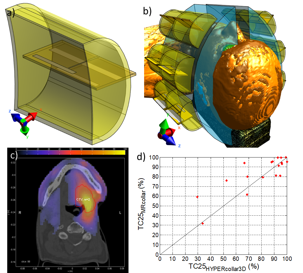
Using electromagnetic (EM) simulation package Sim4Life (v3.4, Zurich Medtech, Zurich, Switzerland), a specific water-filled encasing was designed around our previously designed printed Yagi-Uda antenna (6) (Fig. 1a). Two arrays of six antenna structures were placed in two semi-circular structures (Fig. 1b).
To study the specific absorption rate (SAR) focusing capabilities of this MRcollar model (Fig. 1b), treatment planning using auto-segmented (10 tissues (2)) patient models of 18 patients with advanced head and neck cancers was performed (2). In this step, Sim4Life was used to compute the electric field inside the patient model per antenna (20 periods sinusoidal signal, FDTD discretization of 0.75-2mm, 75MCells). All metallic parts were simulated as perfect electric conducting (PEC) material. The SAR pattern was then optimized using our in-house software tool VEDO (2).
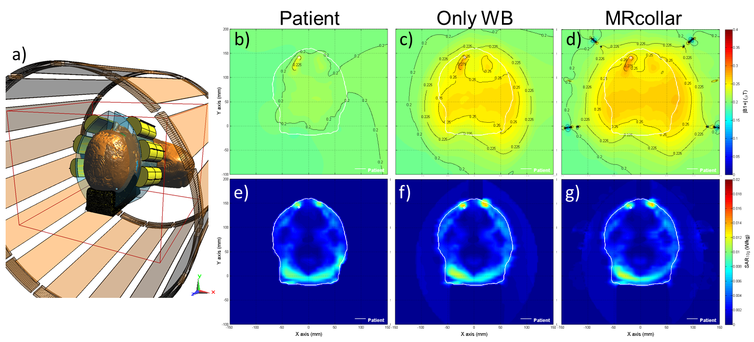
For the B1+ analysis, we first constructed a generic 1.5T 16-rung high-pass birdcage body-coil model (radius=355mm, rung length=670mm) using the birdcage tool in Sim4Life. The coil was excited by two edge sources (64MHz, quadrature mode, 60 periods) and tuned by 32 capacitors placed in two end-rings. The EM field distribution from this simulation was extracted and used as source for subsequent simulations in this study applying the Huygens source technique (10 periods, dimension 400x400x500mm3 covering entire MRlabcollar) (Fig. 2a). Second, the impact of the patient, the waterbolus around the patient and the entire MRcollar on the B1+ and SAR by a birdcage coil were studied.
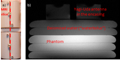
A reduced scale setup consisting of two Yagi-Uda antennas inside their cavities were created (Fig. 3a), and MR imaging using the body coil of a 3T GE MR750w scanner (GE Healthcare, Waukesha, WI) was performed to study image distortions. An FSPGR sequence was used with extended dynamic range: slice thickness 5 mm, field of view 280 x 280 mm^2, matrix 256 x 128, repetition time 68ms, echo time 3.2ms, flip angle = 20°, 2 NEX.
Results
Even for large target volumes, the target coverage of the 25% iso-SAR contour (TC25, (2)) was above 25% (the minimum quality in the clinic): see Fig. 1c for an example. The MRcollar proved worse than the HYPERcollar3D (TC25 <-10%) in only 1/18 cases, but equal in 13/18 and better (TC25 > +10%) in 4/18 cases.
The RF body-coil simulations (Fig. 2) showed that introduction of a waterbolus (WB) increases the |B1+|in the patient model by around 22.8%, but that B1+ homogeneity was not affected. Fig2b-d show high |B1+| distortions near the metal dental implants that were considerable in size for this patient, and Fig. 2d shows the high, but localized, distortion of |B1+|near the antennas. In the patient, an overall increase in |B1+|of 3.4% was observed, probably due to the waterfilled antenna cavities of the MRcollar. Introduction of the MRcollar model showed a negligible further change in predicted induced SAR versus the WB model.
The reduced scale test revealed that, even at 3T, no large artifacts were present (Fig. 3b). Only a very localized image distortion was observed, caused by slightly ferromagnetic connectors of the antennas.
Discussion and Conclusion
Other work showed the potential of using a single integrated antenna array structure for dual-function MR – hyperthermia. However, that approach is hampered by 1) the need for sequential heating and imaging and 2) contradicting requirements in terms of frequency and coil/antenna design. Our design, tailored to reduce systems interaction, different frequencies for imaging and heating enable truly simultaneous operation and the use of the optimal heating frequency regardless of the imaging frequency. Our investigation shows that our novel MR collar design combines the option of excellent power focusing in patients and virtually unobstructed simultaneous imaging with 1.5T and/or 3T MR scanners.Acknowledgements
This study was supported by the Dutch Cancer Society, grant EMCR2012-5472.References
1. Datta NR, Rogers S, Ordonez SG, Puric E, Bodis S. Hyperthermia and radiotherapy in the management of head and neck cancers: A systematic review and meta-analysis. Int J Hyperthermia 2016;32(1):31-40.
2. Paulides MM, Verduijn GM, Van Holthe N. Status quo and directions in deep head and neck hyperthermia. Radiat Oncol 2016;11:21.
3. van Rhoon GC. Is CEM43 still a relevant thermal dose parameter for hyperthermia treatment monitoring? Int J Hyperthermia 2016;32(1):50-62.
4. Verhaart RF, Verduijn GM, Fortunati V, Rijnen Z, van Walsum T, Veenland JF, Paulides MM. Accurate 3D temperature dosimetry during hyperthermia therapy by combining invasive measurements and patient-specific simulations. Int J Hyperthermia 2015;31(6):686-692.
5. Paulides MM, Bakker JF, Hofstetter LW, Numan WC, Pellicer R, Fiveland EW, Tarasek M, Houston GC, van Rhoon GC, Yeo DT, Kotek G. Laboratory prototype for experimental validation of MR-guided radiofrequency head and neck hyperthermia. Phys Med Biol 2014;59(9):2139-2154.
6. Paulides MM, Mestrom RMC, Salim G, Adela B, Numan WCM, Drizdal T, Yeo DTB, Smolders AB. A printed Yagi-Uda antenna for application in magnetic resonance thermometry guided microwave hyperthermia applicators. Phys Med Biol 2017;62(5):1831.
Figures