4424
Switching Impedance Matching and Primary Coil Array Using RF MEMS switches for a Wireless Power Transfer System1Electrical Engineering, Stanford University, Stanford, CA, United States, 2GE Healthcare, Aurora, OH, United States, 3Radiology, Stanford University, Stanford, CA, United States
Synopsis
Wireless power transfer (WPT) inside the MRI bore, as part of completely wireless patient coils, should have minimal RF interactions and be a compact system that allows for flexible placement of the coils while maintaining power transfer efficiency. Changes in coil positions can drastically reduce power amplifier efficiency. Here we present a MEMS based auto-tuning approach to compensate for the varying load seen by the power amplifier. An array primary coils also using high-power RF MEMS devices to steer power to a local secondary coil is also demonstrated.
Introduction
As the number of channels on patient coils continue to increase, there is a proportional increase in the number of connectors, cabling, and RF baluns, all leading to increased patient discomfort. To make large coil arrays comfortable for the patient, it would be ideal to use lightweight, flexible coils that are completely wireless, including wireless power delivery inside the MRI bore. We have previously shown an MRI wireless power transfer (WPT) system operating with minimal RF interactions through the use of RF gating1. However, this system uses a large power amplifier and antenna tuner that cannot be operated inside the magnet. A class-EF power amplifier can be made compact and efficient to operate inside the bore2, but only for a single load impedance. To account for the varying load of the coupled WPT coils an adjustable impedance matching network needs to be used to preserve power amplifier efficiency. Both systems had a single WPT primary coil for flexibility of placement of the secondary but at the expense of lower mutual coupling. Here we present an RF MEMs based impedance matching system that can function inside the MRI bore and a MEMs switched array of primary coils to allow a greater coupling efficiency over a wide area.Methods
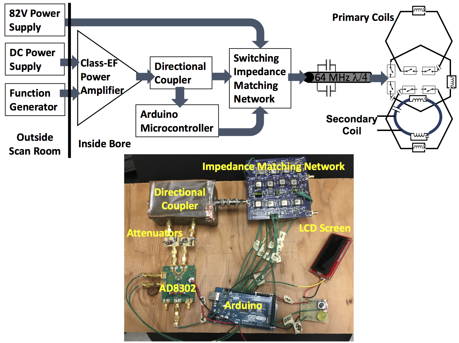
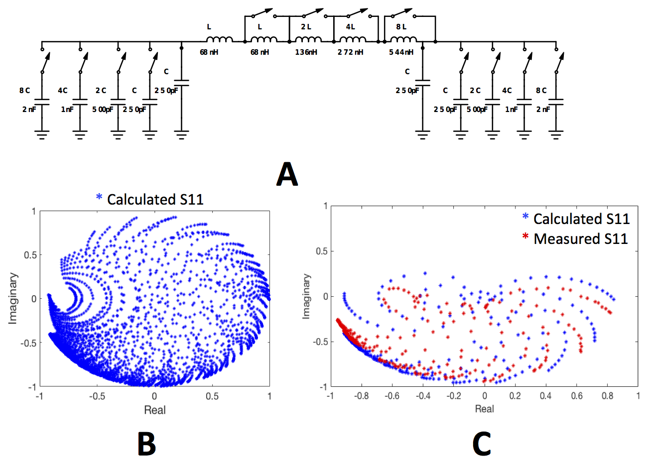
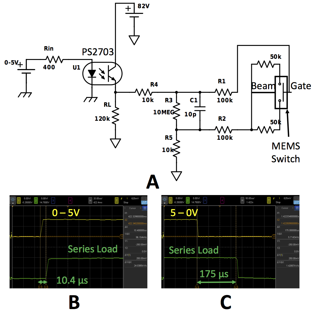
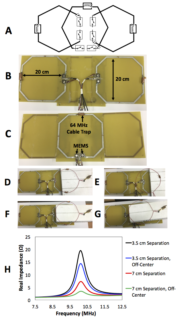
Figure 1 shows a block diagram of our system, as well as a more detailed look at the impedance matching system. A directional coupler measures the forward and reverse voltages as inputs to an AD8302 gain/phase detector. An Arduino microcontroller then samples and converts the outputs to reflection coefficient and impedance which are compared to an impedance lookup table for auto-tuning to the desired 20 Ω load of a class EF amplifier. The impedance matching network is a pi-match with 12 RF MEMS switches, as shown in Figure 2. The inductor and capacitor values are binary weighted in order to cover an even distribution of S11 values. Switching each value individually covers the entire range of S11 values in Figure 4B. For initial testing, capacitors are switched in pairs as a pi-match of equal capacitor values to limit lookup table memory. The calculated S11 values are shown in Figure 4C, with measured values that are slightly shifted due to parasitics on the MEMs matching board. The RF switches themselves need to be able to block the MRI high-power RF levels inside the bore. As a result, we are using the RF MEMS switches presented in 3 with the simple opto-coupled gate drive circuit shown in Figure 3 for control from the Arduino digital pins. Figure 4 shows the basic schematic and construction of the array of primary coils for 10MHz WPT, with the same MEMS switched and gate drive circuit controlling which coil is switched in series with the matching network.Results
Figure 3B and C shows that the falling edge delay is much longer than the rising edge for the MEMS gate driver. This is a property of optocouplers and the fall time delay can be reduced by decreasing the value of RL, however, this leads to a proportional increase in the current and the power drawn from the 82V supply. The primary coils have a Q of about 163 without the MEMS switches. With the addition of the switches and cabling the Q drops to about 44. The impact of adding a secondary coil near the primary coil that is switched in is shown in Figure 4H, demonstrating much better coupled impedances and the ability to transfer power with a few centimeters between coils. With a 20 Ω resistor on the output of the matching network the tuning process achieves a minimum reflection coefficient of about 0.17 and with the coupled coils it is about 0.31.Discussion & Conclusions
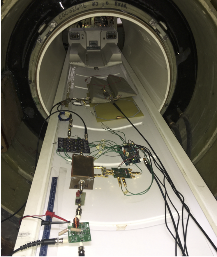
Having primary and secondary coils of the same size optimizes the coupling between them and improves efficiency. Even with greater separation between coils the majority of power will be transferred to the secondary coil. Smaller coils will also pick up less EMF from the scanner. In our preliminary testing, Figure 5 shows the system inside the MRI bore where we were able to tune the coils and transfer and receive power. Future work will include improved organizing of the system cabling and testing the impact of the WPT system on MRI images. The ability to employ high power RF MEMs devices allows easy multiplexing of the primary WPT coils to steer power more locally to a secondary harvesting loop. Similarly, MEMs based auto-tuning provides more flexibility in matching to primary/secondary coil position changes.Acknowledgements
Acknowledgment: We would like to thank GE Healthcare for their research support. This project is supported by grants R01EB008108, P01CA159992, and R01EB019241.References
1. K. Byron, P. Stang, S. Vasanawala, J. Pauly, and G. Scott, A High Power RF Gated Wireless Power Transfer System. Proc. Intl. Sco. Mag. Reson. Med. 24 (2016).
2. K. Byron, F. Robb, S. Vasanawala, J. Pauly, and G. Scott, A MRI Compatible Class-EF Power Amplifier Designed to Drive a Wireless Power Transfer System. Proc. Intl. Sco. Mag. Reson. Med. 25 (2017).
3. D. Spence and M. Aimi, Custom MEMS Switch for MR Surface Coil Decoupling. Proc. Intl. Sco. Mag. Reson. Med. 23 (2015).
Figures