4420
Laplacian-Inspired Design of a Highly-Homogeneous, RF Shielded Magnet for Low-Field TRASE MRI1Physics & Astronomy, University of Manitoba, Winnipeg, MB, Canada, 2Physics, University of Winnipeg, Winnipeg, MB, Canada, 3Phillips, Gainesville, FL, United States
Synopsis
We present a novel Laplacian design method for a finite length magnet with perfect field homogeneity. It will be used to study TRansmit Array Spatial Encoding (TRASE) MRI at low field. As
Introduction
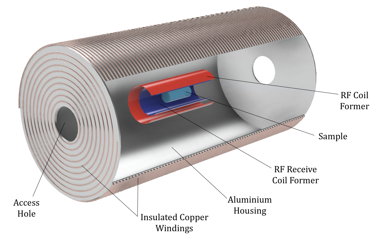
TRansmit Array Spatial Encoding (TRASE) is an MRI method1,2 which uses phase gradients of the B1 field – rather than magnitude gradients of the B 0 field – to achieve spatial encoding. The potential benefits and limitations of this technique are still being explored in both conventional and low-field magnets. This work aims to design a highly homogeneous, low-field magnet (<10 mT) to further studies of TRASE in this regime.3-5 The design method6 is novel and allows for ostensibly perfect field homogeneity. Furthermore, given that TRASE does not require the application of switched B0 gradients, we propose to build the magnet on an aluminum housing which acts both as a heat sink and effective low-frequency RF shield,7,8 as shown in Figure 1.Theory & Methods
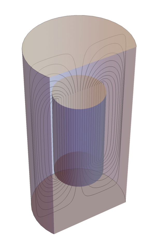
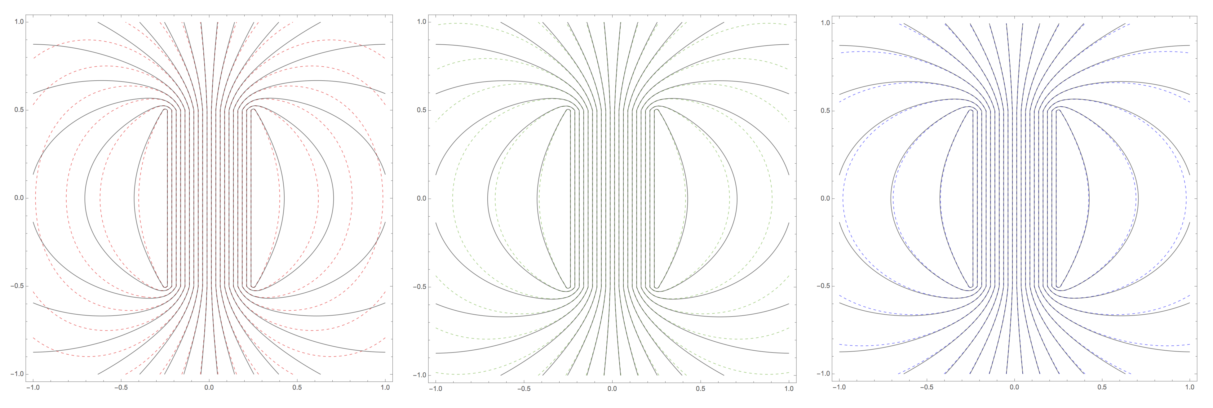
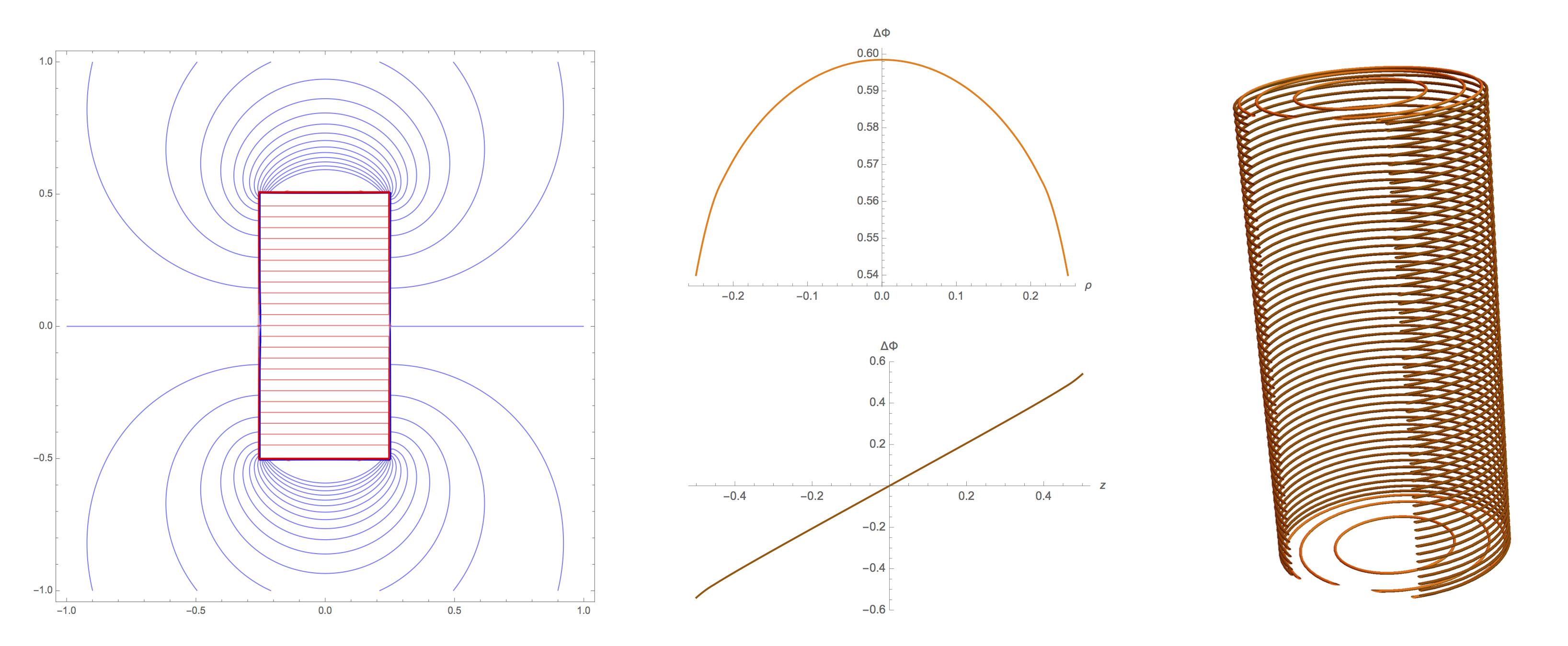
The method is founded upon consideration of two coaxial cylindrical surfaces of finite lengths with surface currents on their bodies and end caps. Boundary conditions are set such that the outer surface perfectly shields the field created. Using finite element methods, the Laplacian of the magnetic scalar potential Φ, and hence magnetic field B, is found in the region between the cylinders (Fig. 2). One is free to specify any solution to the Laplace equation in the inner region, including Φ=-Bz/μ0 which gives a uniform field. By moving the outer surface farther and farther away, we are able to converge to a solution for a single, finite-length cylinder in free space with the perfectly uniform internal field of an infinitely long solenoid (Fig. 3). The discontinuity of the scalar potential across the cylinder boundary is, in fact, equivalent to the stream function,4,6 and, as a result, evenly spaced contours of ΔΦ give the coil winding pattern. Because no current flows at the center of the end caps, access holes can be created in these regions. Figure 4 shows the complete solution process, including the winding pattern for a potential magnet design.Discussion & Conclusion
We have demonstrated a novel design method for a finite length magnet with ideally perfect field homogeneity. Optimization versus the number of wires in the discrete current approximation will be done using Biot-Savart calculations. Our plan is to build such a magnet on an aluminum housing to act as an all-in-one heat sink and electromagnetic shield. It will be used to further study TRASE MRI at low field.Acknowledgements
No acknowledgement found.References
1. JC Sharp, et al. Magn Reson Med. 2010; 63:151 and NMR Biomed. 2013; 26: 1602.
2. Q Deng, et al. Magn Reson Imaging. 2013; 31:891.
3. PJ Nacher, et al. Proc ESMRMB 15, Magn Reson Mater Phy. 2015:28 Suppl.1;S64.
4. S Kumaragamage, et al. Proc ESMRMB 16, Magn Reson Mater Phy. 2016:29 Suppl.1;S34.
5. PJ Nacher et al. and CP Bidinosti et al. This conference.
6. C Crawford (University of Kentucky), private communication.
7. CP Bidinosti, et al. Applied Physics Letters. 2008; 93:174102.
8. S Fahy, et al. Am. J. Phys. 1988; 56:989.
Figures