4415
Comparison of MRI subsystem performances for two models of MRI-guided radiotherapy: MRI-Cobalt-60 versus MRI-Linac1Radiation Oncology, Washington University in St Louis, St Louis, MO, United States, 2ViewRay, Oakwood Village, OH, United States, 3ViewRay, Mountain View, CA, United States
Synopsis
The era of MRI-guided radiation therapy (MR-IGRT) began in January 2014 when the first patient was treated with 60Co under real-time MRI guidance. In 2017, the first FDA-approved MRI-Linac began treating patients. Both systems incorporate a double donut magnet design with a 28 cm gap for the radiation beam. A rotating gantry carries either three shielded 60Co heads or a 6 MV Linac with magnetic and RF shielding. In this study, we compare the MRI subsystem performance between the two systems.
Purpose
There are currently two FDA-approved 0.35 T MRI-guided radiation therapy (MR-IGRT) systems on the market. In January 2014, the first patient was treated using the ViewRay MRIdian (Oakwood Village, OH).1,2 The system uses three shielded 60Co sources that rotate around a low-field MRI. In the summer of 2017, the first patient was treated on the ViewRay MRIdian-Linac. Both systems use the same superconducting double-donut magnet [cryostat OD/ID: 170/108 cm, 28 cm gap between magnets, superconducting shims, split gradient (each side with passive shims, Max. amplitude: 18 mT/m, Max Slew: 200 T/m-s, 80 cm ID), and body transceiver coil (70 cm ID)].
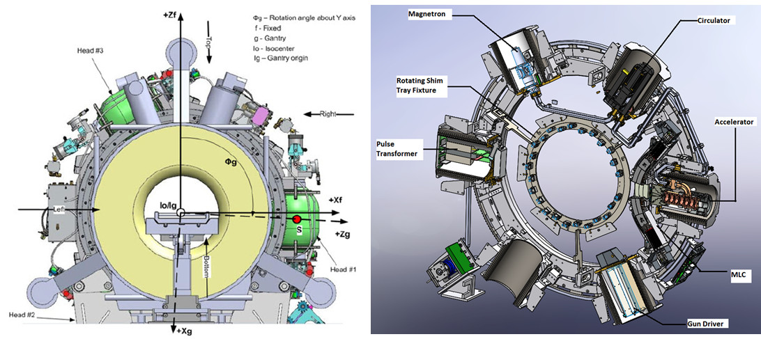
The main difference between the two MR-IGRT systems is the gantry configuration (Fig. 1). The 60Co head assemblies are spaced 1200 apart. The MRI-Linac's rotating gantry carries a 6 MV Linac, related components, and magnetic and RF shielding to maintain MRI image quality (Fig. 2). The Linac and related components are housed inside magnetic shield "buckets" spaced 600 apart. Each steel bucket weighs 227 kg. Passive shims are located around the gantry to compensate for field inhomogeneities caused by the buckets. Gantry shims are not used in the 60Co system.
The purpose of this study was to compare the performance of the MRI subsystems for each model MR-IGRT. The main challenges to MRI performance are: 1) B0 inhomogeneities and instabilities due to the rotating gantry components; 2) RF noise associated with the gantry electronics; and 3) B0 inhomogeneity and gradient nonlinearities with the magnet and gradient gaps.
Methods
Performance tests included National Electrical Manufacturers Association (NEMA) noise tests3-5, American College of Radiology (ACR) quality assurance (QA) tests6, field homogeneity measurements, and spatial integrity measurements. The MRI-Linac tests were conducted before system tune-up completion and system acceptance. The 60Co MR-IGRT results were based on both initial acceptance and recent QA tests.
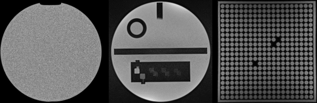
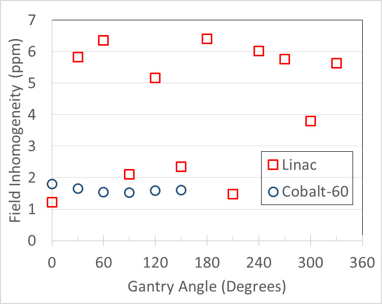
NEMA SNR and field homogeneity tests were performed with a Siemens 24 cm diameter spherical volume (DSV) phantom (Fig. 3). Field inhomogeneity was measured at various gantry angles by acquiring an FID and measuring the full width half maximum (FWHM) of the spectral peak.
ACR tests were performed with a Model J9511 large ACR phantom (J.M. Specialty Parts). ViewRay specifies 25 signal averages for the ACR-T1 and 9 averages for the ACR-T2 acquisitions to improve data analysis. Neither ViewRay model passed the ACR criteria for the low contrast detectability without signal averaging.
Spatial distortion was measured using a Model 76-907 uniformity/linearity phantom (formerly Fluke Biomedical, now HP) with internal dimension 30.6 cm. Custom software was used to measure the distances between individual regions. The interior lengths of the phantom were also measured using MRI and compared with the internal physical dimensions.
Results
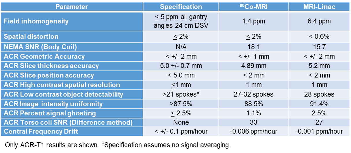
The performance results of the two models are compared in Table 1. The field inhomogeneity versus gantry angle is shown in Fig. 4. The magnets were initially shimmed using a 45 cm DSV field camera to <25 ppm without gradient shimming. The MRI-Linac's field homogeneity was not yet in full compliance. All other parameters meet or exceed performance specifications.
SNR was higher on the 60Co MR-IGRT versus MRI-Linac. However, the Larmor frequencies for the systems are 13.6 and 14.7 MHz for the 60Co and Linac systems, respectively. The 7.5% lower field strength of the 60Co MR-IGRT is unique to our site.
Discussion
The MRI-Linac was not fully optimized at the time of these measurements and was still undergoing tune-up and commissioning. Shim averaging that would reduce the overall inhomogeneity at each gantry angle was not implemented at the time of these results. The average inhomogeneity over all gantry angles was 4.3 ppm so compliance is expected after further shim optimization and averaging. Future system upgrades may include dynamic shimming for each gantry angle.
The NEMA and ACR SNR tests were ineffective for identifying RF interference likely due to their low bandwidths. The 2D cine and 3D TrueFISP sequences used in MRIgRT have typical bandwidths of 1000-1500 Hz/pixel and 300-500 Hz/pixel, respectively. These sequences will put more stress on the system causing more thermal, mechanical, and electrical stress on the components that can degrade image quality. We incorporate system signal and noise stability tests in our monthly QA to detect system degradation.7
Conclusions
Both MR-IGRT system designs represent complex performance challenges for MRI image quality. The field inhomogeneity was slightly worse for the MRI-Linac but this was anticipated due to the larger mass of steel attached to the gantry. We expect both SNR and field inhomogeneity on the MRI-Linac will improve after system tune-up is completed.Acknowledgements
This research was supported by Washington University in St. Louis’s Department of Radiation Oncology.References
1. Mutic S, Dempsey JF. The ViewRay system: magnetic resonance-guided and controlled radiotherapy. Semin Radiat Oncol 2014;24(3):196-199.
2. Wooten HO, Rodriguez V, Green O, Kashani R, Santanam L, Tanderup K, Mutic S, Li HH. Benchmark IMRT evaluation of a Co-60 MRI-guided radiation therapy system. Radiother Oncol 2015;114(3):402-405.
3. NEMA. Determination of Signal-to-Noise Ratio (SNR) in Diagnostic Magnetic Resonance Imaging 2008.
4. NEMA. Characterization of Phased Array Coils for Diagnostic Magnetic Resonance Images 2008.
5. NEMA. Determination of Signal-to-Noise Ratio and Image Uniformity for Single-Channel Non-Volume Coils in Diagnostic MR Imaging 2008.
6. ACR. Magnetic Resonance Imaging Quality Control Manual 2015.
7. McClain B, Curcuru A, Green O, Mutic S, Gach HM. Stability test for MRI quality assurance in radiation therapy. 2017; Denver, CO. p MO-RPM-GePD-IT-1.
Figures