4412
Reverse Engineering of a 7T 16-Channel Dual-Row Transmit Array Coil1Max Planck Institute for Human Cognitive and Brain Sciences, Leipzig, Germany, 2Institute of Neuroscience and Psychology, University of Glasgow, Glasgow, United Kingdom, 3MR Coiltech Limited, Glasgow, United Kingdom
Synopsis
We developed a reverse engineering numerical workflow that yielded a good match between measured and simulated scattering parameters of an inductively decoupled non-overlapped dual-row transmit array for MRI at 7T. We evaluated and compared the performance of different tuning conditions resulted in similar scattering parameters. For the circular polarization mode under-coupled, over-coupled, or mixed tuning conditions resulted in up to 65% variation of different coil losses but small variation of transmit efficiency. For comparisons of array transmit performance, consideration of array-internal losses as well as reflected and radiated power is very important, because their sum can be as high as 71% of the total transmit power.
Introduction:
Manual tuning of a fabricated dual-row coil is extremely laborious. Two coils with the same geometry and similar scattering (S) parameters can provide significantly different transmit performance depending on the tuning condition. Analysis of near-field transmit properties, obtained for different numerical tuning conditions similar to that of a constructed array, is, hence, important for assessing the robustness of array performance. Our current goals are: to obtain possible tuning conditions of a dual-row transmit array loaded by a phantom based on a measured S parameters; to evaluate the impact from different tuning conditions on the obtained transmit efficiency.Methods:
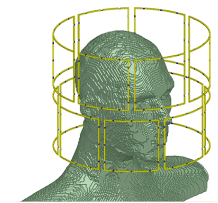
The realistic 3D electromagnetic (EM) model of the dual-row transmit coil (Fig. 1) included all coil construction details for the resonant elements, the phantom used for tuning, and the coil environment. This includes the MRI scanner gradient shield and the magnet bore, which are all simulated with correct dimensions and mechanical and electrical properties. However, the model did not include radiofrequency (RF) cable traps and coaxial cable interconnection wiring. Our investigation was performed using RF circuit (Agilent_ADS2016) and 3D-EM (ANSYS_HFSS_2014) co-simulation as detailed in [1]. The reverse engineering of the transmit coils was based on the minimization of two error functions (EF) at coil operation frequency 297.2MHz. The first EF was used to obtain good coil element match and decoupling according to
$$EF = \sum_0^{16} |S_{xx}-S_{xx_t}|^{2}+\sum_0^{32} 0.5\cdot|S_{xy}-S_{xy_t}|^{2}$$
where Sxx is the element reflection coefficient, Sxy is the element coupling between adjacent elements, Sxxt is the target value for Sxx and was −40 dB, Sxyt is the target value for Sxy and was −20 dB. The second EF was used to obtain tuning condition resulted in a good match between numerical and measured S parameters. Thus, values of Sxxt=−26dB and Sxxt (−10.3dB for the top row and −11.3dB for the bottom row) were taken from the measured S parameters. All results were scaled to a total transmit power of 8W.
Results and Discussion:
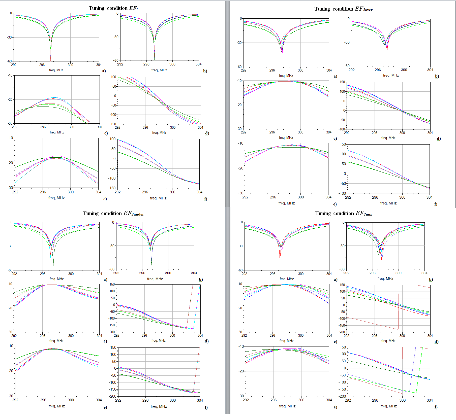
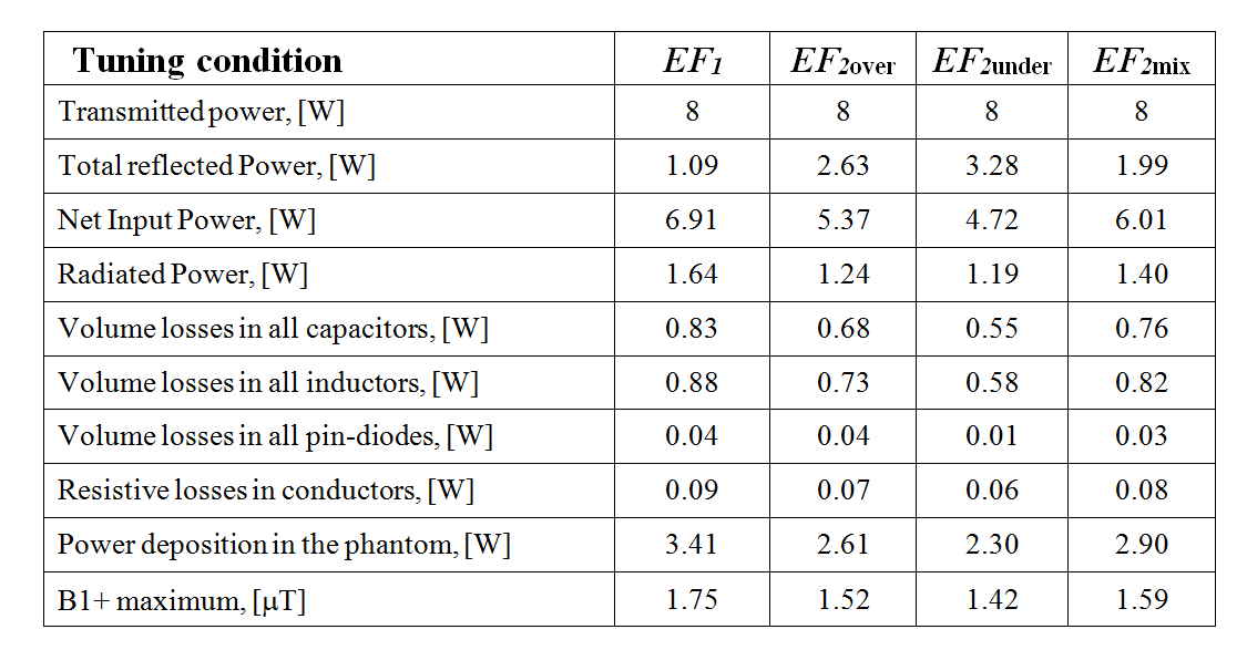
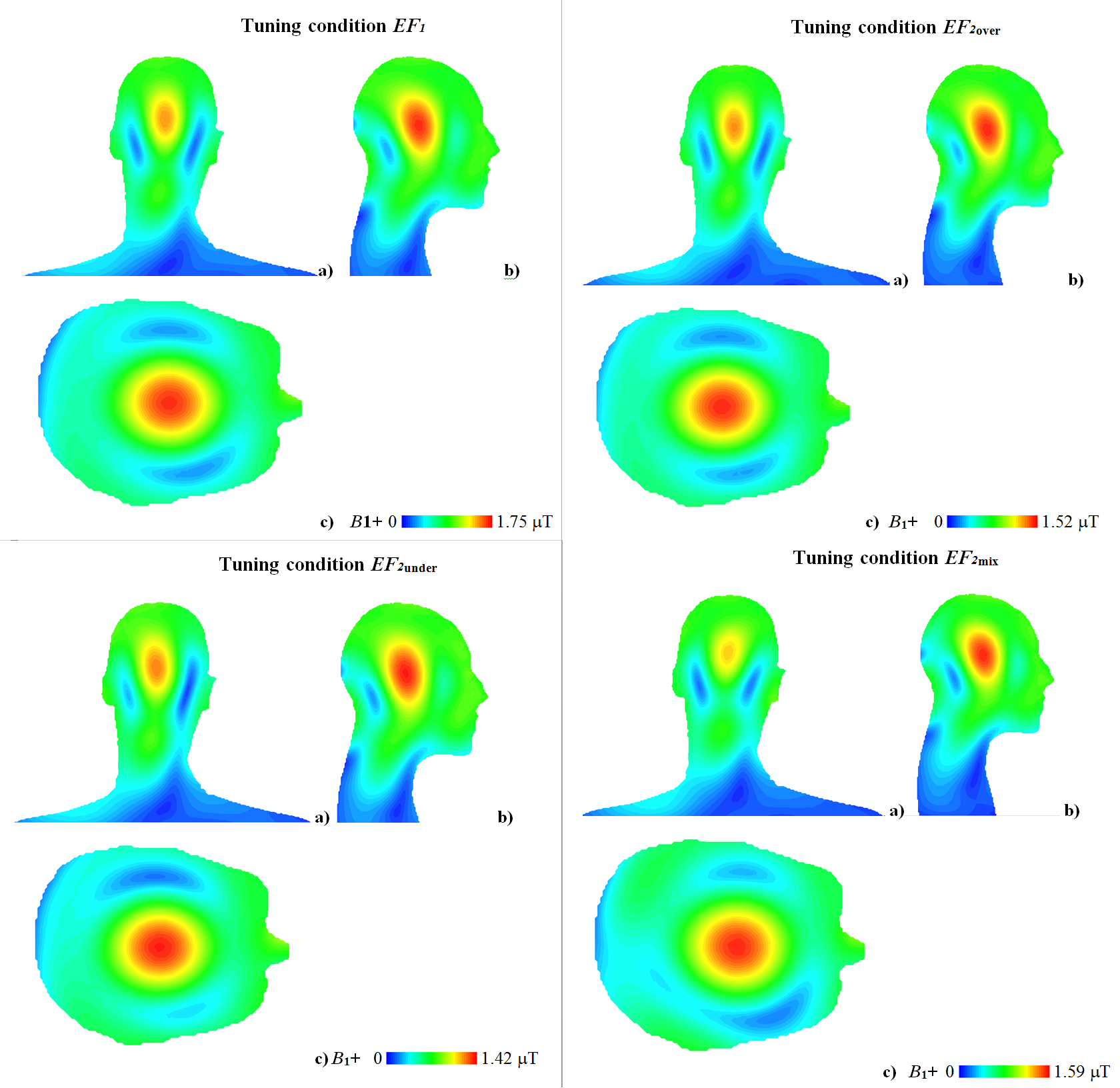
Inductive coupling conditions of two coil elements may be either under-coupled, ideally decoupled, or over-coupled. Due to resistive coupling, it is impossible to obtain Sxy values below the resistive coupling level. Moreover, for an array coil operated at ~300MHz without local shield inductive coupling depends on EM field propagation through different pathways. It resulted in phase shifts of Sxy values that could not be compensated by adjustment of inductor coupling factor (Kinductor). Optimization with the first EF resulted in single set of values for variable capacitors and Kinductor, subsequently referred to as tuning condition “EF1”. The coil appeared to be properly tuned for a given load with Sxx<‒30dB and Sxy<‒17dB. Optimization with the second EF resulted in S parameters identical to measured S parameters (discrepancy less than 1%) and in many sets of values for variable capacitors and Kinductor depending on the type of the optimizer, and start and boundary conditions. These sets can be divided into three major groups on base of residual inductive coupling for adjacent elements: under-coupled cases are subsequently labeled as tuning condition “EF2under”, all over-coupling cases are labeled as tuning condition “EF2over”, and mixtures of under-coupled and over-coupling cases are labeled as tuning condition “EF2mix” (Fig. 2). For EF2under cases, coupling between second adjacent elements was smaller than for EF2over cases but the behavior of the total reflected power (Prefl) was opposite for the circular polarization mode. Prefl varied from ~1W (for EF1) up to 3.28W (for EF2under) (Fig. 3). 64% variation of Prefl for the EF2 cases resulted in only 12% variation of coil transmit efficiency because increase of Prefl was accompanied by decrease of other coil losses. B1+ profiles varied visibly if different tuning conditions were applied (Fig. 4). A homogeneous tissue equivalent phantom was used in this study. Thus, there is insufficient data available for a thorough evaluation of the variation of coil safety efficiency for the different tuning conditions. This can be straightforwardly performed with the developed workflow employing a variety of high-resolution human models used as the coil load. A more detailed coil model with RF cable traps and coaxial cable interconnection wiring is required for detecting elements that increasing coupling between coil elements.Conclusion:
The developed numerical investigation workflow yielded a good match between numerical and measured S parameter data. For the circular polarization mode, under-coupled, over-coupled, or mixed tuning conditions resulted in noticeable variation of different coil losses but small variation of transmit efficiency. The results derived from sophisticated static RF shimming optimization of arbitrary transmit amplitudes and phases, as well as calculation of transmit SENSE pulses and worst-case SAR analysis, should be additionally considered before final decisions are made regarding coil robustness.Acknowledgements
No acknowledgement found.References
[1]. M. Kozlov, R. Turner, "Fast MRI coil analysis based on 3-D electromagnetic and RF circuit co-simulation," J. Magn. Reson., vol. 200, pp. 147-152, Sep. 2009.Figures