4411
Combined EM simulations and measurements of birdcage coil B1+ for designing a 3T multichannel TMS /MRI head coil array1Athinoula A. Martinos Center for Biomedical Imaging, Department of Radiology, Massachusetts General Hospital, Charlestown, MA, United States, 2Worcester Polytechnic Institute, Worcester, MA, United States
Synopsis
The multichannel TMS approach enables steering the stimulation “hot spot” electronically making the execution of concurrent TMS and fMRI experiments potentially more flexible. An integrated multichannel TMS/MRI system is currently under development and here we investigate how TMS coils influences the B1+ field of a birdcage coil. We compare detailed electromagnetic simulations with empirical data using a single three-axis TMS coil element as well as generate simulated data for 4x4 TMS coil array. Both simulations and empirical results indicate that an array of TMS coils should not distort the B1+ significantly at distances bigger than 2cm from the coil.
Purpose
To develop a new type of multichannel TMS/MRI stimulation/imaging array for 3T, we evaluated the effects of the TMS coil elements on the B1+ of a birdcage coil.Introduction
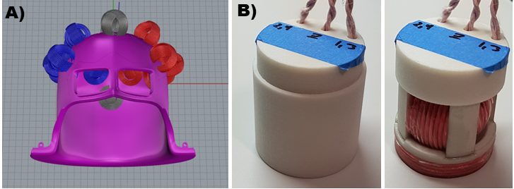
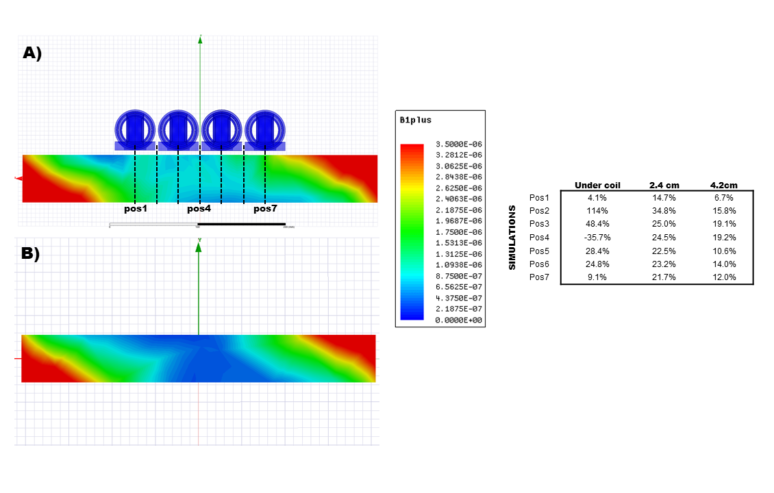
The combination of non-invasive neuromodulation and simultaneous imaging techniques constitutes a powerful approach for neuroscience and potentially treatments. For example, Transcranial Magnetic Stimulation (TMS) during fMRI could help to evaluate causal relationships between the activations of different cortical regions. This combination was presented for the first time by Bohning et al. 20 years ago (1). Dedicated coil arrays have been developed to increase the sensitivity of the MR imaging (2) for these experiments. However, to enable even broader range of potential applications, a multichannel TMS/MRI head coil array for 3 T utilizing a novel three-axis TMS coil design is currently under development (see Fig.1A). When bringing multiple TMS coils inside the MRI scanner it is important to assess the influence of these conducting elements on the RF excitation. Here, we studied the effects of such system on the transmit field based on EM simulations. In addition, a prototype TMS coil element has been fabricated (TristanTechnologies, San Diego, US) and it was used to compare the simulations with experimental data (see Fig.1B).Methods
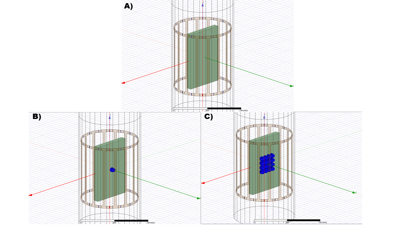
A Skyra body coil (Siemens, Erlangen, Germany) was modeled in HFFS (Ansys, USA) and tuned and matched with a gel phantom as load. The dimensions of the phantom were 60cmx41cmx6cm. Three models were built: (i) the birdcage coil loaded only with the phantom, (ii) the coil loaded with the phantom and a three-axis TMS coil element placed over the center of the phantom, and (iii) the coil loaded with the phantom and 16 three-axis TMS elements distributed in a cartesian grid over the center of the phantom (see Fig.2). To compare the simulations with experimental data, B1+ measurements using the Skyra body coil were done. As load, an in-house built phantom (0.82% NaCl, 17% Agar-Agar) with the same dimensions was used. Two setups were employed: (i) only the phantom and (ii) the phantom and one TMS prototype over the center and placed in the isocenter. Gradient Echo (GRE) images with 6 different flip angles (FA) (TR=3000ms, TE=10ms, FA=10,20,30,50,70 and 90, 50 slices, 3mmx3mmx3mm, MA=96x54) were acquired for each setup to calculate B1+ maps. The measured data was fitted pixel-wise to B1*sin(FA) to calculate the field. The reference voltage was set to be 300 V.Results
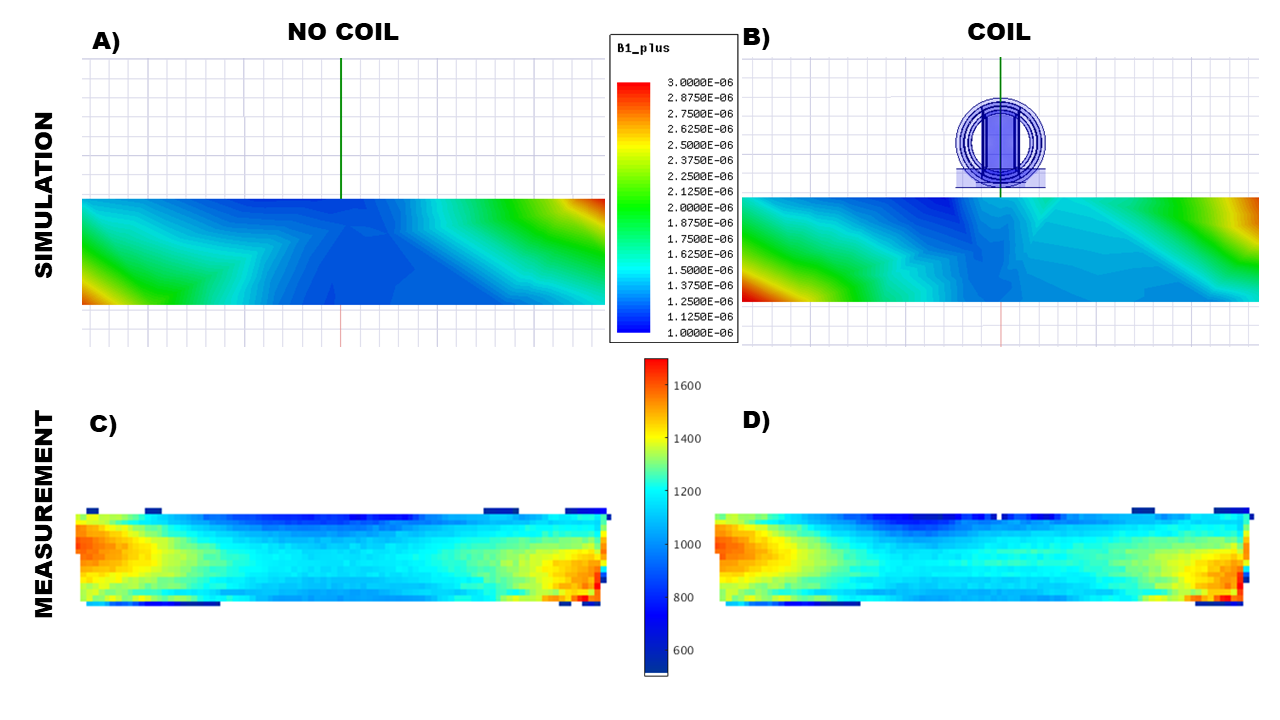
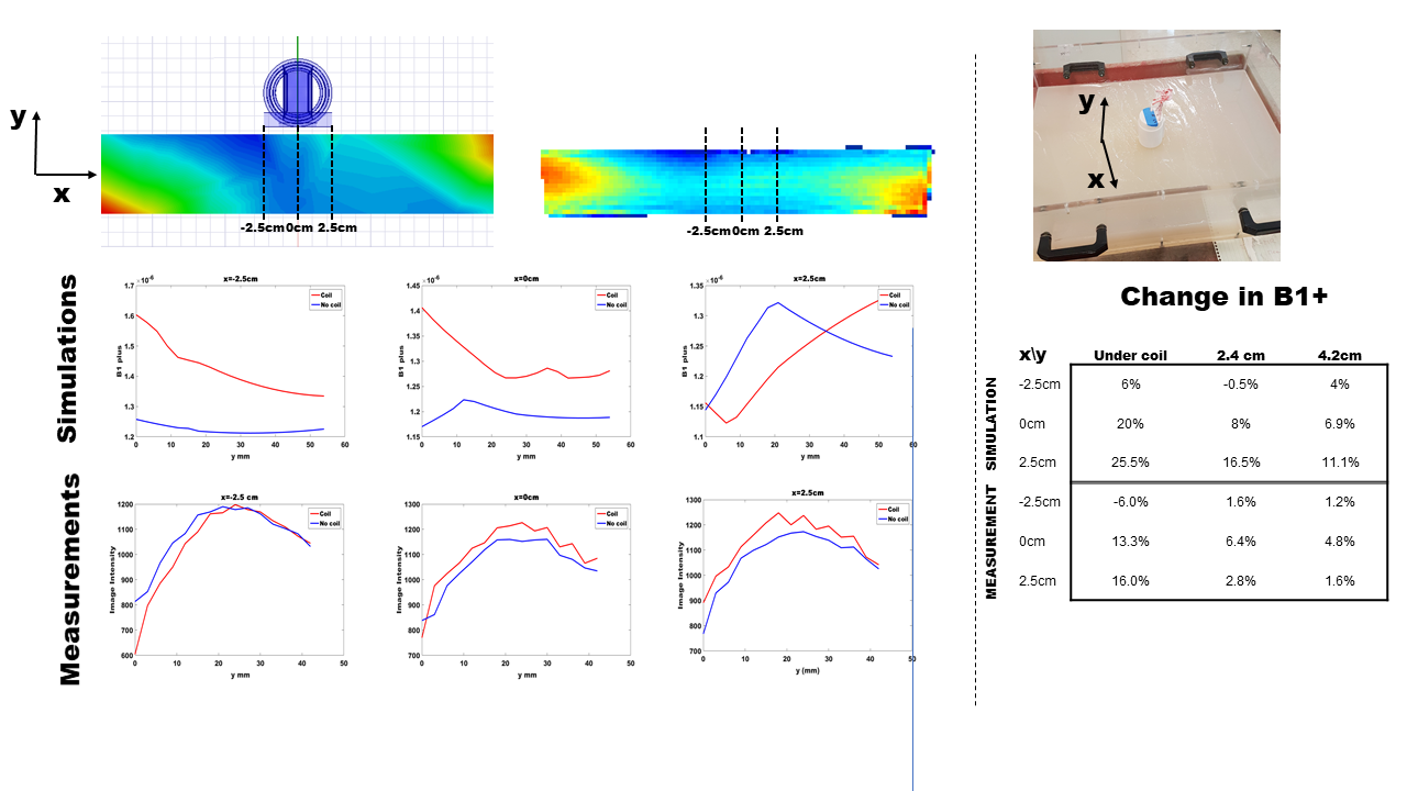
Fig3A and Fig3B show the B1+ simulated over the same field of view as the measurement. Fig3C and Fig3D show the corresponding results of the calculated B1+ field based on the measured data. Profiles of the B1+ at 3 different points on the phantom, for both the simulations and the measurements with and without the coil are shown in Fig4. The table on the figure summarizes the changes of the B1+ when the coil is over the phantom at 3 different depths, for both simulated and measured fields. The simulated B1+ obtained for the multichannel TMS array is shown in Fig5A. For the sake of a clear comparison, Fig5B shows the simulated B1+ for the no coil case. The table on the figure summarizes the changes of simulated B1+ when the array is over the phantom at 3 different depths, for 7 distinct positions.Discussion
The simulated and measured B1+ fields show in general similar characteristics. Both simulations and measurements show enhancement and decrease of the field close to the TMS coil. The profiles show that B1+ enhancement at 4.2cm based on the simulation (between 4-12%) is slightly higher than the measured data (1-5%). This difference is larger for closer regions to the coil. The reason for this is the potential susceptibility effects due to presence of the housing. For the multichannel TMS case, the results show an enhancement of the B1+ at the depth of 4.2cm between 7-19%, and for closer regions, between 15-25%. On the other hand, the field homogeneity at distances greater than 2cm is not significantly affected. No drastic artifacts are expected based on either the simulated or the experimental data. Our conclusion from this study is that an additional transmit coil will not be required even for a large-scale multichannel TMS array positioned inside the MRI environment. However, if using a standard body transmit coil the enhancement of the B1+ must be considered. Further safety assessment must be done and also the effects of the TMS cables should be included in future analysis. The framework presented here may also be useful for other MRI compatible TMS coil design considerations.Acknowledgements
This work was funded by NIH R00EB015445, R01MH111829 and NIH K99EB021349. We want to thank Dr. Douglas Paulson, Mr. Kevin Pratt, Mr. Paul Mascarenas, and Mr. Paul Miller from Tristan Technologies for their contribution in fabricating the coil. We also thank Dr. Yoshio Okada from Moment Technologies and Dr. Bastien Guerin from MGH Martinos Center for valuable discussions on the project.References
(1) Bohning et al.,Invest Radiol,33(6):336-340,1998
(2) Navarro de Lara et al., Magn Reson Med, 74(5):1492-1501,2015
Figures