4410
High Density Volume Array Strategies for SNR and Parallel MRI1Invivo, Gainesville, FL, United States, 2Philips, Gainesville, FL, United States
Synopsis
Most receive array coils are made of many various shapes of loop coils with different arrangements. In practice, the final goal for a good performance array coil is to find a combination of these loop coils such that improved optimal signal-to-noise ratio (SNR)1-3 and reduced parallel MRI g-factor3 can be achieved in the same time. Here we study four different loop coil arrangements for a head array coil. The simulation results shed some light on optimal loop arrangements and performance expectations.
Introduction
Most receive array coils are made of many various shapes of loop structures/modes with different combinations. In practice, the final goal for a good performance array coil is to find a combination of these loop structures/modes such that improved optimal signal-to-noise ratio (SNR)1-3 and reduced parallel MRI g-factor3 can be achieved in the same time. Here we study four different loop coil arrangements for a head array coil. The simulation results shed some light on optimal loop arrangements and performance expectations.Methods
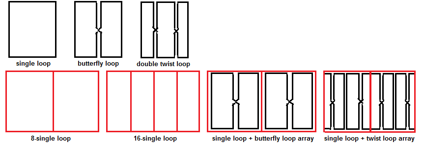
Figure 1 shows three loop shapes: a single loop, an equal-area butterfly loop and a double twisted loop with center area twice of the side areas. Four array coils are simulated by placing these loops in circular formation without overlapping: (1)8-channel array made of eight single loops; (2)16-channel array made of 16 single loops; (3) a 16-channnel array made of 8 single loops and 8 butterfly loops, where butterfly loop is nested inside single loop; (4) a 16-channel array made of 8 single loops and 8 double twisted loops, where twisted loop is in the middle of (gap region) two adjacent single loops. For comparison, these four arrays have the same diameter of 28cm and axial length of 18cm for human head study. An heterogeneous human head model is used to load the simulated arrays with brain centered. For simplicity, we assume ideal decoupling between each loop element by driving each tuned loop coil separately at 128MHz. Results are normalized to unit current along each loop for further analysis. Software tool Sim4Life is used in this study.Results
Total resistance of each loaded loop element is RT = Rs (1+α), where Rs is the sample resistance and α represents the coil losses. In practice, α is determined by Q-measurement of the loop coil with α = QL/(QU-QL). First, we build four loops with shapes similar to elements of four simulated arrays on bench. Q-measurements are conducted with a cylindrical phantom (4.5g/L NaCl). The distances from phantom to loop conductors are at 1cm and 3.5cm and measured α are 0.05 and 0.17 for larger loop, 0.09 and 0.3 for smaller loop, 0.09 and 0.53 for butterfly loop, 0.26 and 2.39 for double twisted loop. Considering the distance between head tissues to array conductors ranging from 2.5cm to 6cm, we simply use these fixed α values for following analysis: 0.15 for large loop, 0.25 for small loop, 0.5 for butterfly loop and 1.5 for double twisted loop.
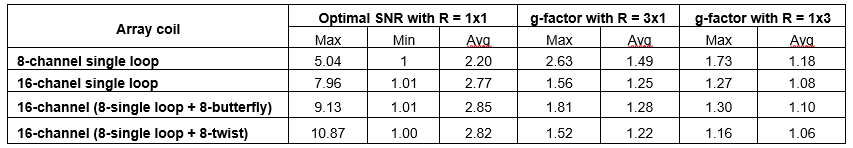
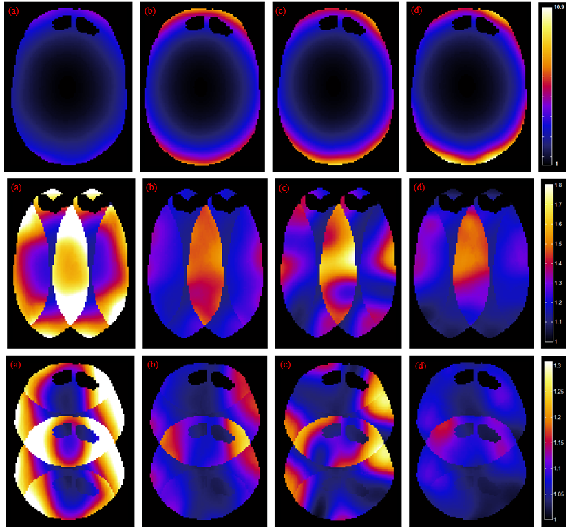
Figure 2 shows the calculated optimal SNR over the center transverse slice of the head model with R = 1x1 for four simulated arrays. As expected, higher SNR is seen in the peripheral area near the loop conductors. Lowest SNR is in the center area away from the loops. Near the peripheral region 16-channel array has higher SNR than the 8-channel array. For the same 16-channel arrays, the combination of large single loops with double twisted loops shows higher SNR. Notice that the different arrangements of the loops seem not to affect SNR in the center region. This may be expected from sensitivity limits of array coils4. Figure 2 also shows two examples of SENSE g-factor for R = 3x1 (left-right direction) and R = 1x3 (anterior-posterior direction), respectively. Table 1 lists the numerical values of maximum, minimum and average SNR over the center slice, which are normalize to the minimum SNR of 8-channel single loop. SENSE g-factors are also given. Considering the size of the single loop in 16-channel array is half of that in the 8-channel array, the advantages of overall higher SNR and less g-factor from the reduced loop size and increased channel count is evident. The 16-channel Loop+Twisted-Loop array has a combination of better peripheral SNR than the 16-channel Loop-array, and also better g-factor than the 16-ch Loop-Butterfly array, and therefore seems to be more beneficial than just reducing single loop size for increasing channel count.
Conclusions
Here we simulated four head array coils based on
different combinations of single loops, butterfly loops and double twisted
loops. Ignoring the loop coil coupling, the simulation
results show generally the expected advantages of reduced loop size and more
receive channels for imaging region near the coil conductors, with little
performance gain in imaging regions far away from surface coils. We found that
combining double-twist loops with larger loops gave better combined SNR and
g-factor compared to smaller loops size array or larger loops combined with
butterfly elements. As array designs increase in channel count and tighter
fitting, rather than simply using smaller loop sizes, the combination of large
single structures/modes with double twisted structures/modes may be beneficial for both SNR and SENSE
imaging.Acknowledgements
No acknowledgement found.References
1. Roemer P, et. al, MRM 16(2): 192 (1990)
2. Pruessmann, KP, et. al., MRM 42(5): 952 (1999)
3. Ohliger MA, et al, MRM 54:1248 –1260 (2005)
4. Roemer P, Edelstein WA. Proc SMRM 1987. p 410
Figures