4407
Evaluation of RF Shielding Effectiveness by Method of Moments1GE Global Research, Niskayuna, NY, United States
Synopsis
In MRI system, RF shielding is designed to isolate the RF coil from outside conductive objects. Usually simulation is done with only RF coil and RF shielding being included and the impact from outside objects could be qualitatively estimated by limiting the fringe field of the RF coil to a certain level. In this work, the impact from gradient coil to the RF coil can be examined quantitatively rather than qualitatively via the S-parameters of the RF coil being studied with Method of Moments. which is very useful for the RF shielding design.
Introduction
In MRI system, RF shielding is designed to isolate the RF coil from conductive objects outside, such as the gradient coil, the high order shim coils and other electrical components[1]. In principle, RF shielding should provide excellent shielding at RF frequency (128MHz for 3T), while at lower gradient coil frequency (~10KHz), it should be as transparent as possible. These conflicting demands sometimes result in a simple RF shielding supporting too much eddy current as well as Joule heat induced by gradient pulse, or on the contrary, not providing enough shielding for RF[1]. Usually simulation is done with only RF coil and RF shielding being included and the impact from outside objects could be qualitatively estimated by limiting the fringe field of the RF coil to a certain level. But for recent developed high field high performance MR systems, the RF shielding should be carefully designed due to the high strength gradient coil and the unsymmetrical patient bore profile[2,3] In this work, the S-parameters of the RF coil were studied with Method of Moments(MoM)[4,5]. The effectiveness of the RF shielding could be clearly examined with the existence of the gradient coil for the first time. It could provide guidance for the RF shielding design for advanced MRI system[3].Method
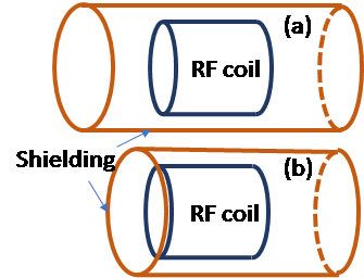
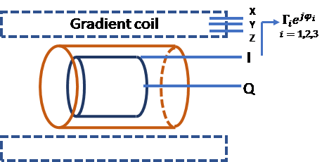
A full length (the perfect shielding) and a partially cut short RF shielding, such that being not long enough at one end of the RF coil (the imperfect shielding), were included in the model, respectively(Fig.1). Firstly, a birdcage coil together with the RF shielding was tuned and matched[6] at 128MHz with a load. Then the gradient coil was imported into the model. Since the characteristics of the ports connecting to the gradient coil is complicated and could be variant from system to system according to the RF frequency characteristics of the power driver, the cable length and the connection methods, etc., they were simplified as S-parameters $$$\Gamma_ie^{j\phi_i}$$$, where $$$\Gamma_i\in[0,1],\phi\in[-\pi,\pi)$$$ and $$$i$$$ is the port index of gradient coil(Fig.2). We variated their values to watch how the S-parameters of the RF coil were changed.Results and Discussions
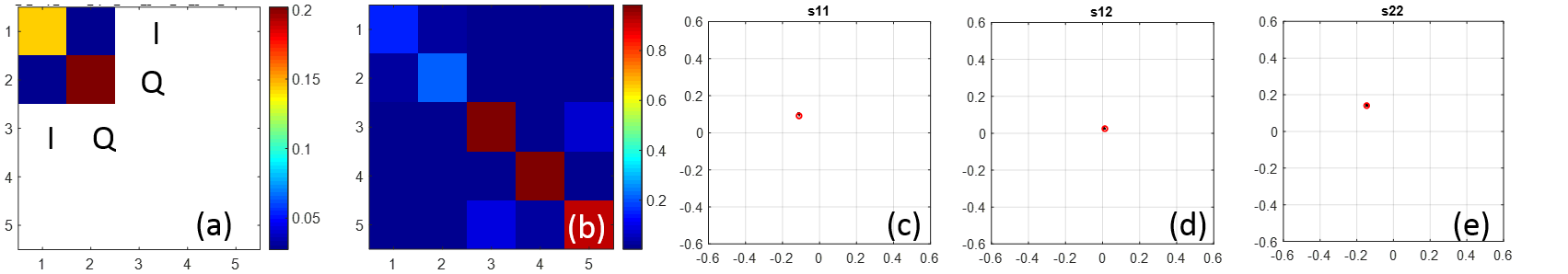
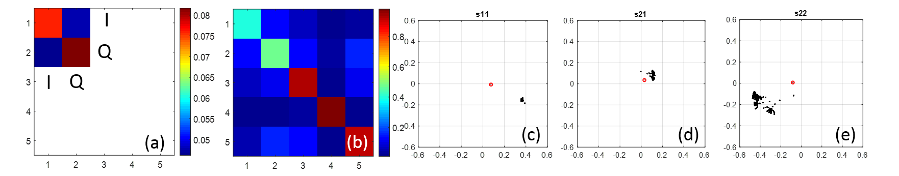
Although FDTD is a high efficient simulation method for problems involving high-heterogeneous materials, it might be less efficient for targets such like gradient coil and high-order shims, which are composed of lots of curved conductors with very narrow gaps in between. To accurately represent the shape of conductors and to avoid the misinterpretation of the gaps, a fine voxel mesh size is needed. 1mm mesh size for the large volume of the gradient coil system can easily make voxel number arriving several G and thus long simulation time is needed. To extract S-parameters of a N-port coil demands N iterations of simulations. On the other hand, Method of moments, provides the accurate conformal mesh only on the surface of the conductors and the homogeneous dielectric material boundary. Meanwhile, the frequency domain solver of MoM needs only one shot on the working frequency, and the excitation for N-port is to change of the right-hand excitation vectors of the matrix equation. This makes MoM a relative better method for this problem when no complex phantom or human body is involved. Fig.3 shows for the good shielding case, the introduction of the gradient coil does not change the S-parameters of RF coil, while for the insufficient shielding case, the S-parameters of the RF coils were shifted from almost zero to a high-level value due to the existence of the gradient coil and the ineffectiveness of the shielding, which means the RF coil can see the gradient coil when the shielding is not very well functional(Fig.4). Note that for the perfect shielding case, the RF coil itself was not very well matched in this study, but it didn't affect the conclusion.
Conclusion
In this work, we provided a method to study how the gradient coil affects the RF coil. The impact on the S-parameters of the RF coil can be examined quantitatively rather than qualitatively, which is useful for the RF shielding design.Acknowledgements
This work is funded in part by DoD W81XWH-16-2-0054.References
[1] Lee B, Watkins R, Chang C, and Levin C, Low eddy current RF shielding enclosure Designs for 3T MR applications, MRM, 2017.
[2] Mathieu J. Lee SK, et al, Development of a Dedicated Asymmetric Head-only Gradient Coil for High-Performance Brain Imaging with a High PNS Threshold, ISMRM 2015,1019
[3] Foo T, Graziani D, et al., MAGNUS head-only gradient Coil: An ultra-high efficiency gradient coil for imaging the brain, submitted to ISMRM 2018
[4] Harrington R, Field Computation by Moment Methods, Wiley-IEEE Press, 1993
[5] Feko (Altair Engineering) was used to perform the MoM simulations.
[6] Kozlov M, Turner R, Fast MRI coil analysis based on 3-D electromagnetic and RF circuit co-simulation, JMR, 2009, 200, 147-152
Figures