4404
Accelerating the Co-Simulation Method for Fast Design of Transmit Array Coils: An Example Study on a Degenerate Birdcage Coil1Electrical and Electronics Engineering Department, Bilkent University, Ankara, Turkey, 2National Magnetic Resonance Research Center (UMRAM), Ankara, Turkey
Synopsis
The co-simulation method suffers local minima during the design of a transmit array coils. In this study, our purpose is to utilize an equivalent circuit model of the coil and analytical calculations to provide a proper initial guess for co-simulation method. For the proof of concept, we designed and constructed an eight-channel head-degenerate birdcage coil (DBC) for a 3T scanner using this method which decreased the optimization time by more than 6000 fold.
Introduction
In spite of the advantages of using transmit array coil for the MRI,1-5 the design and manufacturing of such coils are significant challenges due to the mutual coupling between elements of the array.
The co-simulation method which was proposed by Kozlov et al.6 reduced the difficulties of RF coil designs. The optimization component of the co-simulation method is difficult because of existence of many local minima. To solve this problem, many randomly chosen initial guesses were used to ensure that global minimum has been achieved.7,8 This makes the optimization process time-consuming.9
In this study, we utilized a modified equivalent circuit model of the coil and analytical calculations in order to provide a proper initial guess for the co-simulation method. As a case study, we designed an eight-channel head degenerate birdcage coil10 (DBC) for a 3T MRI scanner.
Theory and Method
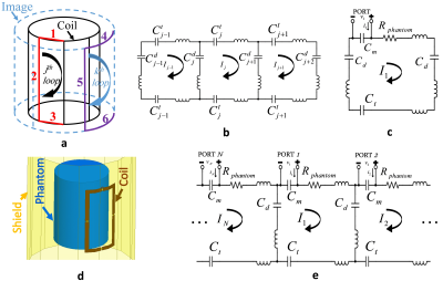
The equivalent circuit model11 of a shielded DBC consists of self- and mutual-inductances (Fig. 1a). $$${L_{j,p,k,q}}$$$ represents the self- or mutual-inductance of $$${p^{th}}$$$ segment in $$${j^{th}}$$$ loop with $$${q^{th}}$$$ segment in $$${k^{th}}$$$ loop. The Kirchhoff’s voltage law for the $$${j^{th}}$$$ loop can be written in the form of a matrix equation as follows:
$$\bar{\bar{K}}\cdot\bar{I}=\frac{1}{{{\omega^2}}}\bar{\bar{H}}\cdot\bar{I}$$
$$$\bar{I}$$$ is a vector of mesh currents shown in Fig. 1b. Moreover, the elements of matrices $$$\bar{\bar{K}}$$$ and $$$\bar{\bar{H}}$$$ can be represented as11:
$${K_{j,k}}=2({L_{j,1,k,1}}-{L_{j,1,k,3}}-{L_{j,1,k,4}}+{L_{j,1,k,6}})+\sum\limits_{m=0}^1{\sum\limits_{n=0}^1{{{(-1)}^{m+n}}({L_{j+m,2,k+n,2}}-{L_{j+m,2,k+n,5}})}}$$
$${H_{j,k}}=\left({\frac{2}{{C_j^t}}+\frac{1}{{C_j^d}}+\frac{1}{{C_{j+1}^d}}}\right){\delta_{j,k}}-\left({\frac{{{\delta_{j,k+1}}}}{{C_j^d}}+\frac{{{\delta_{j,k-1}}}}{{C_{j+1}^d}}}\right)$$
$${\delta_{j,k}}=\begin{cases}1&j=k\\0&j\neq k\end{cases}$$
In the case of DBC, analytic formulas presented in Grover’s book12 are used for the inductance calculations. We assumed coupling between nonadjacent loops (channels) is negligible, so the problem can be simplified to three adjacent loops and the decoupling capacitance can be calculated as:
$$C_j^d=-\frac{1}{{{\omega^2}{K_{j,j-1}}}}$$
Assuming perfect decoupling between all channels, whole array structure can be treated as N separated single-loops, so that the tuning capacitance becomes
$$C_j^t=\frac{2}{{{\omega^2}}}\left({\frac{1}{{{K_{j,j}}+{K_{j,j-1}}+{K_{j+1,j}}}}}\right)$$
Up to this point, the resistive effect of the phantom was ignored, however, for the matching purpose this value becomes critical13-15 (Fig. 1c). We achieved a good prediction on this value by performing an EM simulation (HFSS, ANSYS, Canonsburg, PA, USA) of a single loop in the presence of the phantom (Fig. 1d) by assuming perfect decoupling between the channels. For the model in Fig. 1c, the resistive effect of the phantom can be formulated as:
$${R_{phantom}}=real\left\{{\frac{j}{{\omega{C_m}\left({j\omega{C_m}{Z_{simulation}}-1}\right)}}}\right\}$$
where $$${Z_{simulation}}$$$ is the impedance at the port that is obtained from the EM simulator. Finally, the general equivalent circuit model for DBC including loading effect of the phantom (Fig. 1e) is utilized for the calculations.
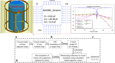
In co-simulation method6, all lumped elements were replaced with excitation ports inside an EM simulator’s environment. In the case of the DBC, we replaced all capacitors on the coil with 50ohm lumped ports in HFSS (Fig. 2a). The resultant S-matrix was exported to a microwave circuit simulator (AWR Corp. El Segundo, CA, USA). In AWR environment, initial capacitors (determined by analytic calculations explained above) were placed at the pins corresponding to capacitors (Fig. 2b). Utilizing the optimization tool in AWR and using the gradient optimization algorithm with the minimum reflected power constraints, the proper capacitor values were obtained. Fig. 2c shows the S-parameters corresponding to the simulated circuit in AWR after optimization. Overall design process is shown in the flow-chart in Fig. 2d.
Results
Defining the cost function as total reflected power, the optimization tool converged to various total reflected power values by randomly choosing 1000 initial guesses (triple-sets of capacitor values in the range of 1pF to 100pF). Fig. 3a shows the converged cost values for different initial guesses.
Fig. 3b demonstrates the number of iterations for different initial guesses. Total number of iterations for 1000 randomly chosen initial guesses was more than 794000, however, calculated initial value provides the same results in 123 iterations. So, for this case-study the proposed algorithm speeds-up the optimization process more than 6400 times.
In Fig. 3c, the cross marker, corresponding to the analytically calculated initial values, offers the minimum cost value to be achieved using the least iterations.
An eight-channel DBC (Fig. 4) inside a slotted RF-shield16,17 was constructed using the optimized capacitor values. The S-parameters were measured at 123.2MHz.
The MRI experiments were performed on a 3T scanner (Siemens Tim Trio, Erlangen, Germany) and B1-maps corresponding to each channel were obtained using the Bloch-Siegert18,19 method (Fig. 5).
Conclusion
In this work, we proposed a method based on the equivalent circuit model to accelerate the co-simulation method for design of a transmit array coil. As a case-study, an eight-channel DBC for 3T head-imaging was designed and constructed using the proposed method. For this case-study, the proposed method achieved a speed up over 6000 fold in the optimization process, compared to the existing method.Acknowledgements
No acknowledgement found.References
1. Katscher U, Börnert P. Parallel RF transmission in MRI. NMR in Biomedicine. 2006 May 1;19(3):393-400.
2. Zhu Y. Parallel excitation with an array of transmit coils. Magnetic Resonance in Medicine. 2004 Apr 1;51(4):775-84.
3. Pauly J, Nishimura D, Macovski A. A linear class of large-tip-angle selective excitation pulses. Journal of Magnetic Resonance (1969). 1989 May 1;82(3):571-87.
4. Hardy CJ, Cline HE. Spatial localization in two dimensions using NMR designer pulses. Journal of Magnetic Resonance (1969). 1989 May 1;82(3):647-54.
5. Tropp J. Image brightening in samples of high dielectric constant. Journal of Magnetic Resonance. 2004 Mar 31;167(1):12-24.
6. Kozlov M, Turner R. Fast MRI coil analysis based on 3-D electromagnetic and RF circuit co-simulation. Journal of magnetic resonance. 2009 Sep 30;200(1):147-52.
7. M. Kozlov and R. Turner, “Analysis of rf transmit performance for a multi-row multi-channel mri loop array at 300 and 400 mhz,” in Microwave Conference Proceedings (APMC), 2011 Asia-Pacific, pp. 1190–1193, IEEE, 2011.
8. M. Kozlov and R. Turner, “Analysis of rf transmit performance for a 7t dual row multichannel mri loop array,” in Engineering in Medicine and Biology Society, EMBC, 2011 Annual International Conference of the IEEE, pp. 547–553, IEEE, 2011.
9. Yan X, Ma C, Shi L, Zhuo Y, Zhou XJ, Wei L, Xue R. Optimization of an 8-channel loop-array coil for a 7 T MRI system with the guidance of a co-simulation approach. Applied Magnetic Resonance. 2014 May 1;45(5):437-49.
10. Alagappan V, Nistler J, Adalsteinsson E, Setsompop K, Fontius U, Zelinski A, Vester M, Wiggins GC, Hebrank F, Renz W, Schmitt F. Degenerate mode band‐pass birdcage coil for accelerated parallel excitation. Magnetic resonance in medicine. 2007 Jun 1;57(6):1148-58.
11. Jin J. Electromagnetic analysis and design in magnetic resonance imaging. CRC press; 1998 Sep 29.
12. Grover FW. Inductance calculations: working formulas and tables. Courier Corporation; 2004.
13. Hoult DI, Lauterbur PC. The sensitivity of the zeugmatographic experiment involving human samples. Journal of Magnetic Resonance (1969). 1979 May 1;34(2):425-33.
14. Harpen MD. Eddy current disruption: Effect on nuclear magnetic resonance coil impedance and power loss. Medical physics. 1989 Sep 1;16(5):781-4.
15. Novikov A. Advanced theory of driven birdcage resonator with losses for biomedical magnetic resonance imaging and spectroscopy. Magnetic resonance imaging. 2011 Feb 28;29(2):260-71.
16. Hayes CE, Eash MG, inventors; General Electric Company, assignee. Shield for decoupling RF and gradient coils in an NMR apparatus. United States patent US 4,642,569. 1987 Feb 10.
17. Roemer PB, Edelstein WA, inventors; General Electric Company, assignee. RF shield for RF coil contained within gradient coils of NMR imaging device. United States patent US 4,871,969. 1989 Oct 3. 18. Sacolick LI, Wiesinger F, Hancu I, Vogel MW. B1 mapping by Bloch‐Siegert shift. Magnetic Resonance in Medicine. 2010 May 1;63(5):1315-22.
19. Turk EA, Ider YZ, Ergun AS, Atalar E. Approximate Fourier domain expression for Bloch–Siegert shift. Magnetic resonance in medicine. 2015 Jan 1;73(1):117-25.
Figures


