4401
Fast Optimization Method for RF Coil Array Geometry in a Post-Processing Step1Center for Biomedical Imaging, Department of Radiology, NYU School of Medicine, New York, NY, United States, 2Center for Advanced Imaging Innovation and Research (CAI2R), NYU School of Medicine, New York, NY, United States
Synopsis
In this work we propose a novel single-run simulation method for RF coil design spanning enough of the design space to provide a clear intuition on optimal coil design, offer a benchmark SNR, and predict coil losses and coupling. It is based on the combination of conductors and sources to emulate coil arrays in a post-processing step. We demonstrated our method's potential for the optimization of an RF coil array for imaging of the rat limb at 7T. We validated our method using electromagnetic (EM) field simulations.
Introduction
Traditional radio-frequency (RF) coil optimization is time consuming, as it requires a simulation run for each coil geometry, without ever knowing how much room for improvement there is. Flexible methods exist to find the maximum possible SNR at a given voxel, independent of any particular coil design, with a single simulation run. This can be achieved by using a large number of surface current modes1 or infinitesimal dipoles2. However, these methods lack the intuition for practical coil design and a realistic prediction of conductor and lumped element losses and coupling.
Here we propose a novel single-run simulation method for RF coil design spanning enough of the design space to provide a clear intuition on optimal coil design, offer a benchmark SNR, and predict coil losses and coupling. Our method is based on the combination of conductors and sources to emulate coil arrays in a post-processing step. We demonstrated our method's potential for the optimization of an RF coil array for imaging of the rat limb at 7T. We validated our method using electromagnetic (EM) field simulations.
Methods
The presented optimization method for RF coil arrays allows to vary not only the lumped element distribution3 but also the geometry of a coil array in a post-processing step. This is achieved by enabling or disabling currents in conductor patches that are connected by sources to emulate a desired coil geometry. By knowing the scattering matrix and the corresponding EM-fields, the resulting EM-field distribution can be computed4.
As an example we chose the optimization of a 2-channel receive RF coil array for imaging of the rat knee using contrast agents at 7T, the region-of-interest (ROI) is depicted in Fig1. For this application SNR uniformity is required since we aim to perform longitudinal follow-up animal studies after a single administration of a contrast agent.
We optimized the average and minimal SNR, and the normalized standard deviation in the central transversal plane of the ROI. The uniformity along the z-direction was achieved by the length of the coil elements.
The SNR distribution in the transversal plane depends primarily on the location of z-directed conductors. Therefore, we chose to model 13 dipoles surrounding the knee. Loop and ladder coils were chosen as candidates, promising a high SNR. They were emulated by driving selected dipoles with appropriate phase shifters in a post-processing step, Fig2a-c. By neglecting circumferential currents we expect a globally lower SNR.
Finite element method software HFSS was used to simulate all designs. The simulation setups are shown in Fig2. The simulation setups for validation are shown in Fig2d.
To validate the method we emulated 6 loop coil elements of different width with our method, and simulated those loops. The resulting SNR for both cases was normalized to the respective maximal mean SNR. All SNR values for the two methods evaluated thereafter were normalized to this SNR value.
To obtain a benchmark we computed the maximum possible SNR that can be achieved in the design-space in each voxel by using the 13 dipole elements as coil elements; along with the optimal weights for the voxel with the lowest optimal SNR1.
The optimal design was found by evaluating all possible configurations of loop and ladder coils.
Results and Discussion
The fast optimization method agrees well with the traditional optimization approach, see Fig3. The lowest possible SNR in the optimization space is achieved in the bottom voxel, see Fig4a. The corresponding optimal weights are shown in Fig4c, predicting that it is necessary to place conductors close to the extreme positions in order to boost the minimal SNR. Applying these optimal weights for the bottom voxel for all voxels yields a uniform SNR distribution across the transversal plane, as shown in Fig4b. The receive properties of optimal coil array candidates, as well the hypothetical coil arrays described in Fig3a-b, are shown in the table in Fig5a. As a winning design we chose a hybrid loop and ladder coil, whose top conductor is split in two, shown in Fig5b.Conclusion
A fast optimization method based on post-processing of a single simulation run of conductor patches connected by sources is presented, applied and validated.
For our particular application we used 13 dipoles to emulate loop and ladder coils and their combination for rat knee imaging at 7T. In this example we chose to exclude circumferential currents for a faster analysis, introducing an acceptably small error. The obtained relative SNR maps were sufficient to find the optimal design: a hybrid loop and ladder coil, whose middle conductor is split in two. This was confirmed with EM-simulations.
Acknowledgements
No acknowledgement found.References
1. Lattanzi, R., & Sodickson, D. K. (2012). Ideal current patterns yielding optimal signal-to-noise ratio and specific absorption rate in magnetic resonance imaging: computational methods and physical insights. Magnetic Resonance in Medicine, 68(1), 286–304. http://doi.org/10.1002/mrm.23198
2. Guérin, B., Villena, J. F., Polimeridis, A. G., Adalsteinsson, E., Daniel, L., White, J. K., & Wald, L. L. (2017). The ultimate signal-to-noise ratio in realistic body models. Magnetic Resonance in Medicine, 78(5), 1969–1980. http://doi.org/10.1002/mrm.26564
3. Kozlov, M., & Turner, R. (2009). Fast MRI coil analysis based on 3-D electromagnetic and RF circuit co-simulation. Journal of Magnetic Resonance, 200(1), 147–152. http://doi.org/10.1016/j.jmr.2009.06.005
4. C. M. Collins, A. G. Webb, J. Paska, "Electromagnetic Modelling." Magnetic Resonance Technology: Hardware and System Component Design, edited by A. G. Webb, The Royal Society of Chemistry, 2016, pp.331-377
Figures
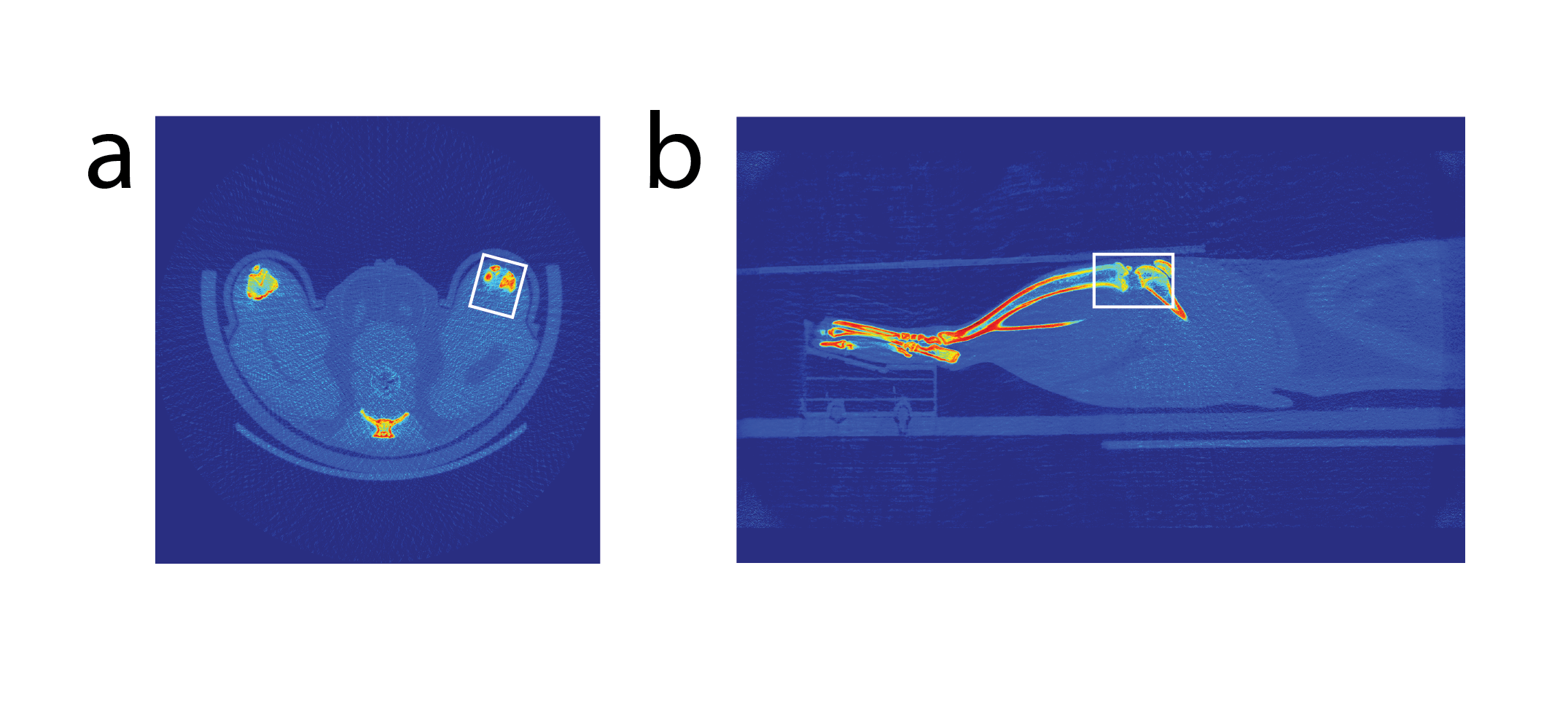
Figure 1: CT image of the rat knee. The box indicates the region of interest (ROI).
a) Transversal slice through the center of the ROI.
b) Sagital slice through the center of the ROI.
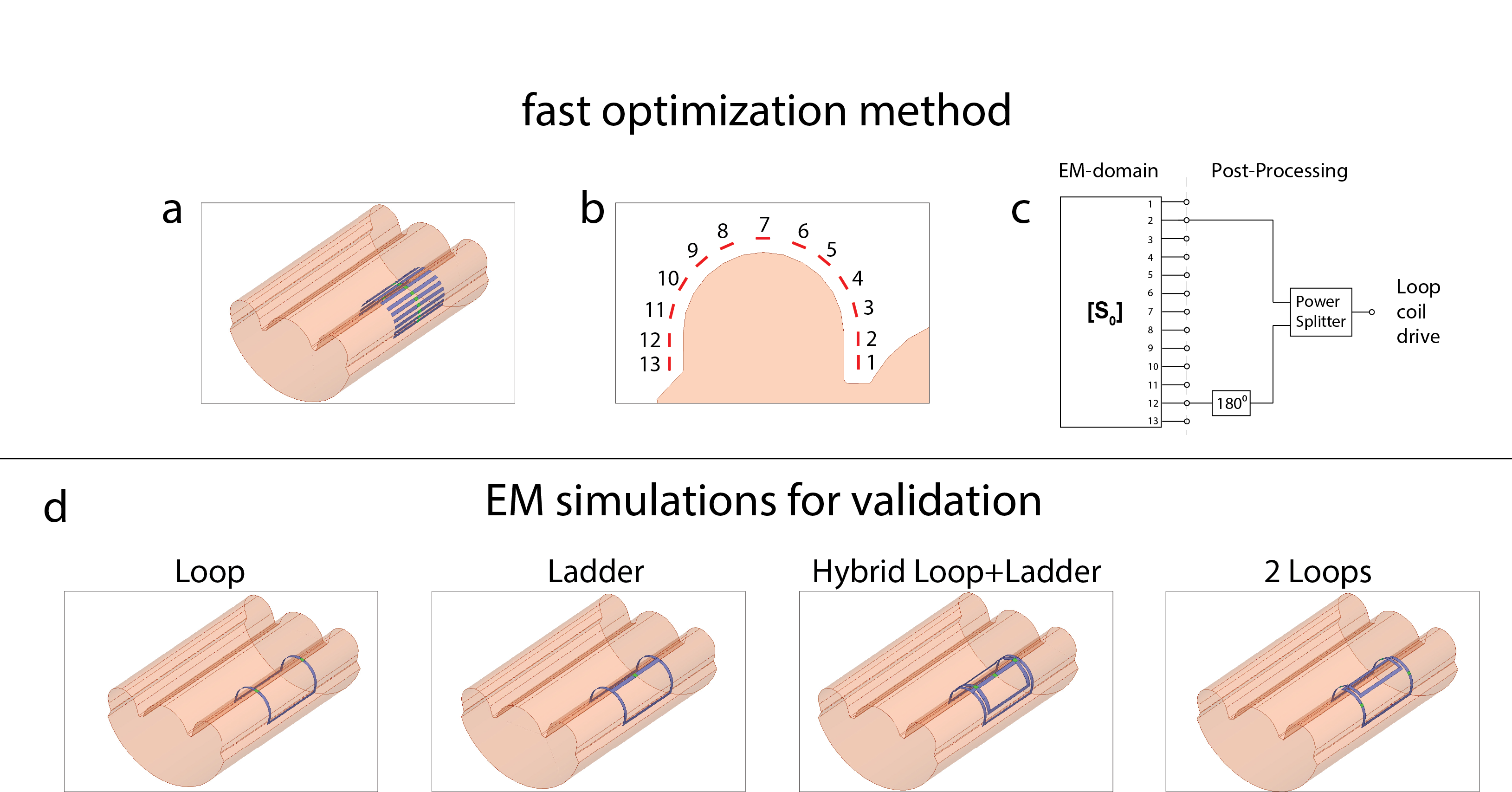
Figure 2: Setup for the fast optimization method (top row) and simulation setups for the validation (bottom row).
a) EM-simulation setup for the fast optimization method consisting of 13 3.5 cm long dipole elements surrounding a homogeneous phantom representing the rat knee. With homogeneous tissue like properties (εr=50, σ=0.6 S/m)
b) Numbering of the dipole elements in the cross-section of the setup.
c) Setup in post-processing emulating a loop coil, by using a power splitter and a 180 degree phase shifter.
d) EM-simulation setups for validation.
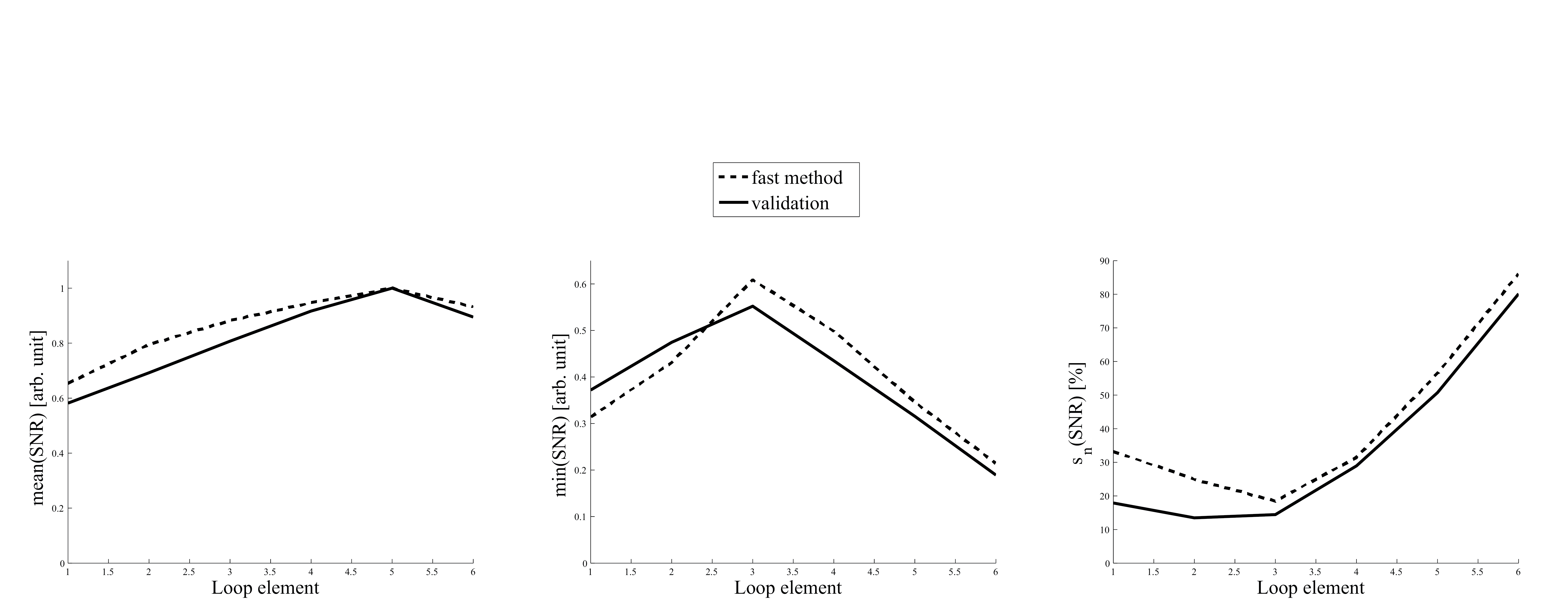
Figure 3: Validation of the optimization method. The line labeled fast method shows the prediction of Rx properties based on our presented method based on a single simulation run. The line labeled as validation shows the prediction of the Rx properties based on 6 EM-simulations one for each width of the loop coil element. Loop element 1 is the widest.
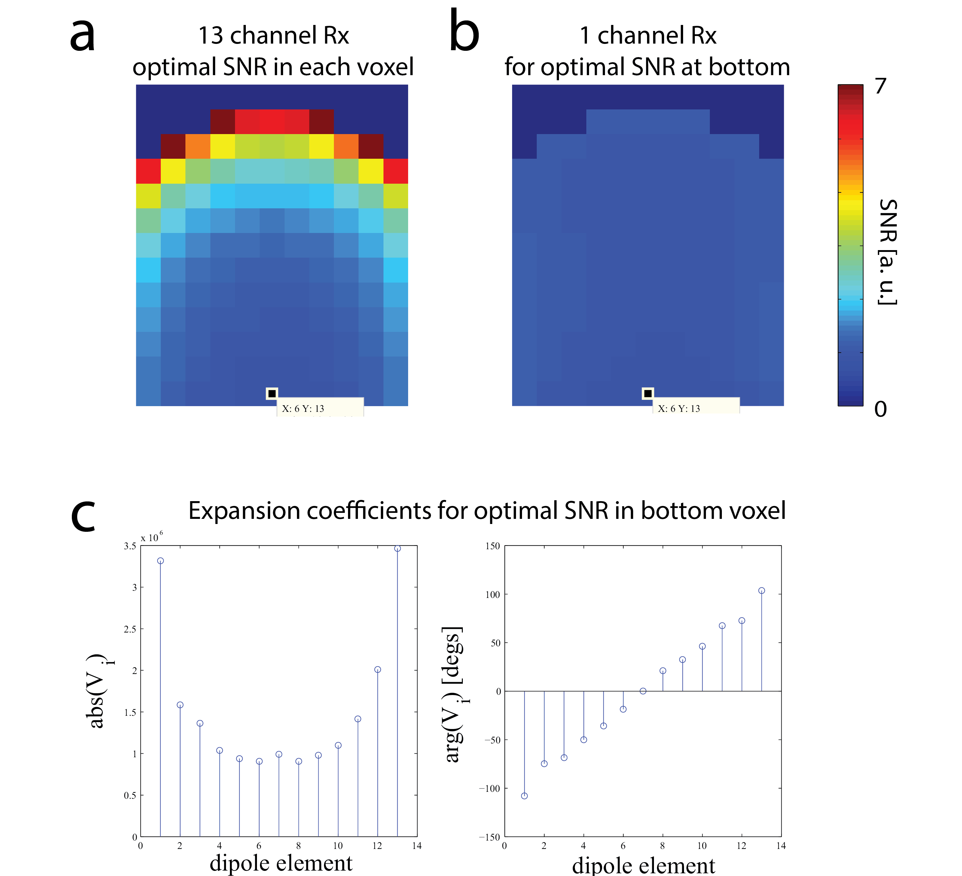
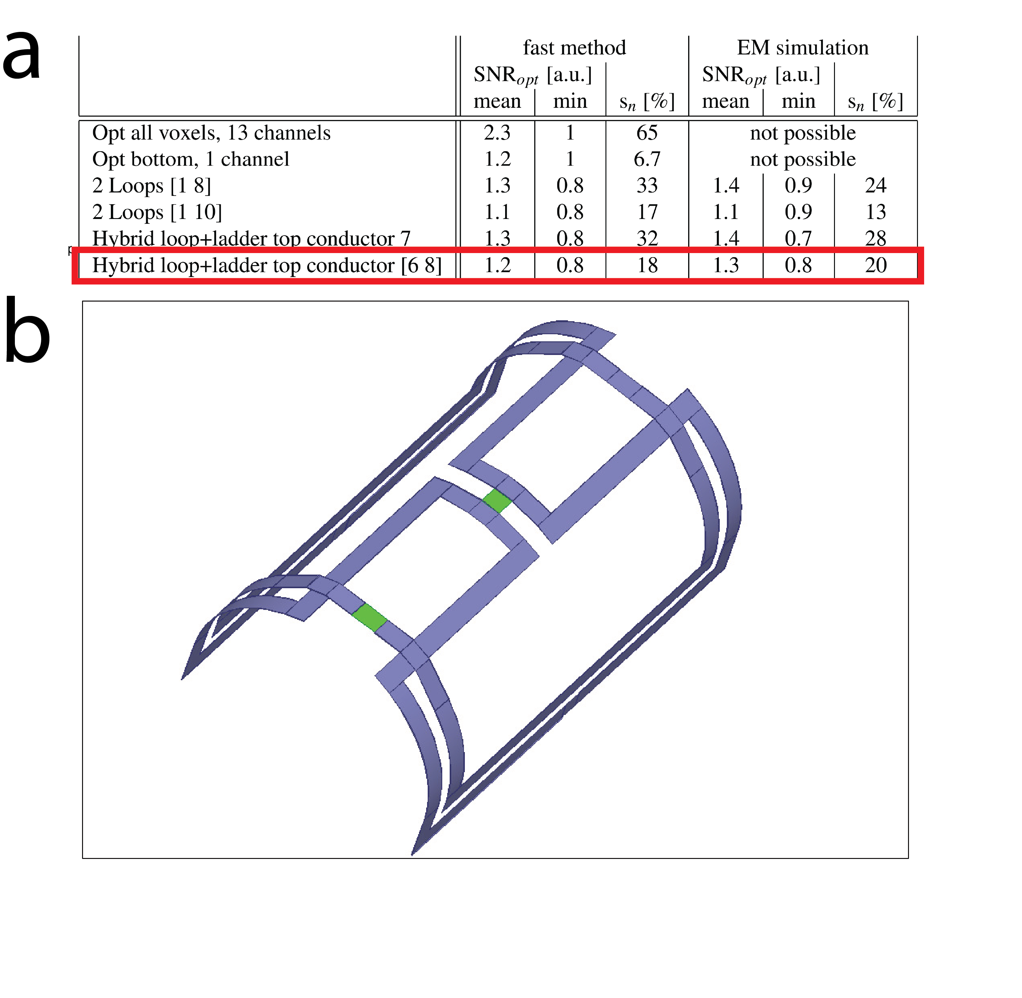
Figure 5: Optimal designs.
a) Rx-properties of the best performing coil array candidates. The left three rows show the Rx-properties as predicted by our fast optimization method based on a single simulation run. The right three columns show the Rx-properties as predicted by a simulation modelling the coil array necessitating for each array a different EM-simulation. The first two rows show the Rx properties of hypothetical coil arrays described in Figure 3. The winning design, a hybrid loop and ladder coil whose top conductor is split is highlighted in the table.
b) Chosen optimal design, sources are highlighted in green.