4400
Design and simulation of dual-band dipole antenna for 1H/31P at 9.4T MRI1Institute of Neuroscience and Medicine – 4, Forschungszentrum Jülich, Jülich, Germany, 2Department of Neurology, Faculty of Medicine, RWTH Aachen University, JARA, Aachen, Germany
Synopsis
The resonance frequency of a dipole antenna is defined by its length (λ/2). The use of LC traps at specific locations within the dipole antenna generates additional resonances. We designed a dual-band dipole antenna tuned to 400 MHz for 1H and 160 MHz for 31P with the aid of an LC trap. The length of the dipole antenna was shortened to 32 cm by introducing end meanders and this concept was also expanded to form a 4-channel array. The performance of the dual-band dipole antenna was simulated and the feasibility of using it as an antenna array is demonstrated.
Purpose
MR measurements using non-proton nuclei (X-nuclei) are of great interest due to the availability of complementary information. Moreover, ultra-high field (UHF) MRI has provided a means to acquire high quality X-nuclei images and spectra as well as 1H signal 1, 2. Since the signal strength of X-nuclei is considerably lower compared to that of 1H, X-nuclei coils tend to be combined with the 1H elements for B0 shimming and scout imaging. However, conventional birdcage coils are not utilised for whole brain imaging at ultra-high field, e.g. 9.4T due to the technical difficulty, such as the requirement of extreme low capacitor values3. A dual-band dipole antenna (DBDA) with LC traps was first introduced in RF antenna engineering in 1941 and modified with advanced trap design4,5. A dipole antenna generally resonates at a single frequency determined by its physical length (λ/2). With the insertion of LC traps symmetrically onto each side of the dipole antenna, a dual resonance structure can be generated. The resonance frequencies of the DBDA can be simply tuned by varying the locations and values of the traps. In this study, we designed and simulated the DBDA and evaluated its feasibility for 1H/31P MR applications at 9.4T.Methods
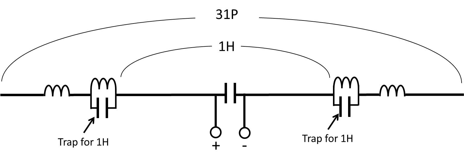
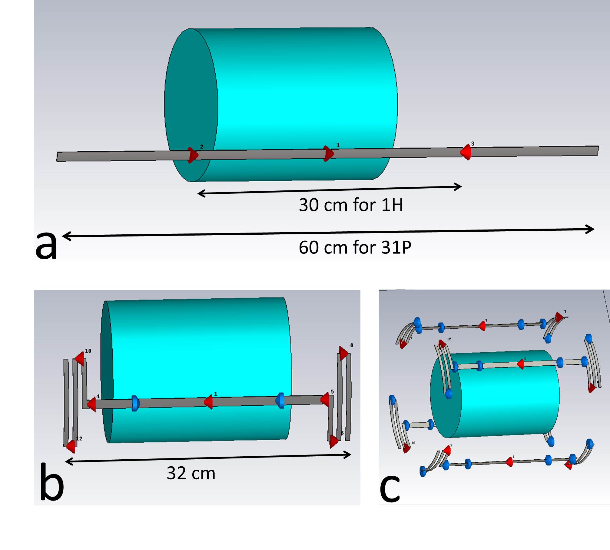
Fig. 1 shows the schematic diagram of the LC trapped DBDA operating at two resonance frequencies (160 and 400 MHz), in which the LC traps can block current on the higher frequency (400 MHz). Performance of the DBDAs was evaluated by means of the finite integration technique simulations using CST. As shown in Fig. 2, three coil geometries, a single-channel straight DBDA, and a single-channel DBDA with meander ends and a 4-channel DBDA array were simulated. The length of the single-channel straight DBDA was 60 cm and the LC traps were placed 15 cm away from the centre, so that the dipole antenna can generate a 400 MHz standing wave between the traps. Since the length of the straight DBDA is too long for human brain applications, the antenna was shortened to 32 cm in length by modification of its end in a meander configuration6. Additional inductors (4 x 80 nH) were inserted to tune the 32 cm dipole antenna. The 4-channel short DBDA array (28 cm diameter) with meander ends was then designed and simulated. A cylindrical water phantom (diameter =16 cm, length = 20 cm, ɛ = 80 and σ = 0.5 S/m) was used as a load in all simulations. The efficiency of the single-channel straight DBDA was compared with that of single-tuned 30 cm (400 MHz) and 60 cm (160 MHz) dipole antennas to evaluate losses due to the LC traps.Results and Discussion
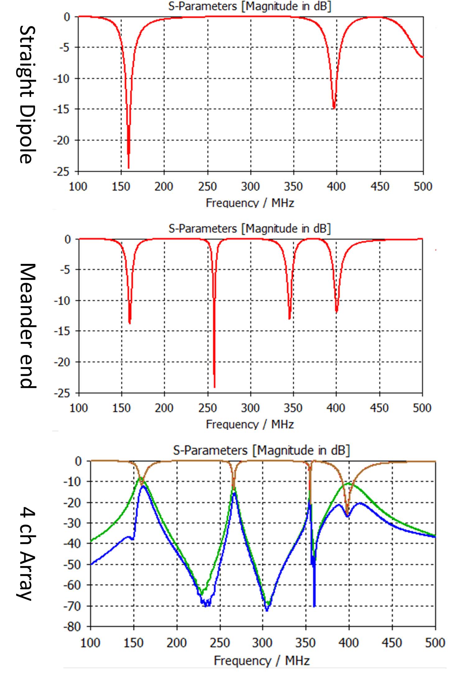
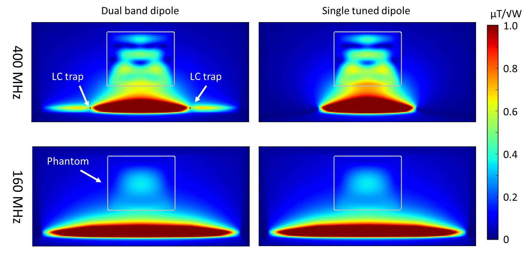
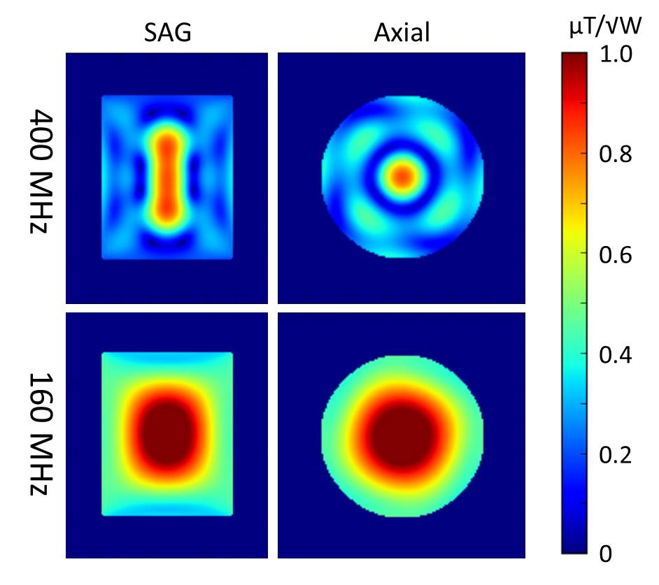
Fig. 3 shows the input reflection (S11) of DBDAs as well as the crosstalk between elements in the array configuration demonstrating the straight DBDA was successfully tuned to 160 MHz and 400 MHz. The DBDA with meander ends and the 4-channel array were also tuned well to 160 MHz and 400 MHz. However, additional resonance modes were generated due to the actual implementation of the LC traps and the values chosen for the inductors. The isolations between nearest neighbours were -11.2 dB and -8.6 dB in average at 400 MHz and 160 MHz, respectively. Fig. 4 shows the B1+ field distributions of the single straight DBDA. At 400 MHz, the B1+ field distribution was concentrated only between LC traps generating a standing wave pattern, while, at 160 MHz, the B1+ field was distributed over the whole dipole antenna. The averaged transmit efficiencies of DBDA at 400 MHz and 160 MHz were approximately 7% and 1% lower compared to the single-tuned dipole antennas. As shown in Fig. 5, the B1+ field distributions generated by the 4-channel DBDA array at 400 MHz is found to be focused at the centre of the phantom, which is general B1 field behaviour in high permittivity material at UHF MRI7. In contrast, at 160 MHz, the DBDA array provided more uniform pattern over the phantom.Conclusions
The DBDA with LC traps was successfully tuned to 400 MHz and 160 MHz for 1H/31P at 9.4T, and it was possible to realise whole volume excitation with a 4-channel array. Because the tuning of DBDA is straightforward and it can easily be extended into an array capable of covering the complete human brain, the DBDA design is a good candidate for 1H/X-nuclei application at ultra-high field.Acknowledgements
No acknowledgement found.References
1. Collins CM, Smith MB. Signal-to-noise ratio and absorbed power as functions of main magnetic field strength, and definition of “90°” RF pulse for the head in the birdcage coil. Magn. Reson. Med. 2001.
2. Rodgers CT, Clarke WT, Snyder C, et al. Human cardiac 31P magnetic resonance spectroscopy at 7 tesla. Magn. Reson. Med. 2014.
3. Chin C-L, Collins CM, Li S,et al. Design of Specified-Geometry Birdcage Coils with Desired Current Pattern and Resonant Frequency. Concepts Magn. Reson. 2002;15:156–163.
4. K MH. US PATEMT, Radio antenna system. 1941.
5. Parrini F, Papi F, Pieraccini M. Double resonance L-C trap for dual-band dipole antenna. In: 2014 IEEE Conference on Antenna Measurements Applications (CAMA). ; 2014. pp. 1–4.
6. Raaijmakers AJE, Italiaander M, Voogt IJ, et al. The fractionated dipole antenna: A new antenna for body imaging at 7 Tesla. Magn. Reson. Med. 2015.
7. Collins CM, Liu W, Schreiber W, et al. Central brightening due to constructive interference with, without, and despite dielectric resonance. J. Magn. Reson. Imaging 2005.
Figures