4399
Simulation study about New RF loop coil with homogenous 7T B1 field1Philips Healthcare, Pewaukee, WI, United States
Synopsis
A loop coil design
with homogenous B1 field and competitive sensitivity for 7T MRI was
presented. The proposed coil was able to align on ROI unlike the asymmetric
segmented loop coil design. The calculated B1 field uniformity and
coil sensitivity of the proposed coil was superior to the asymmetric segmented
loop coil as well as the loop coil with symmetrically distributed capacitors. The eight channels volume shaped loop array constructed
by the proposed design loops was simulated. The proposed design will
potentially help the construction of larger size loop arrays to cover more
imaging volume at 7T and higher.
Introduction
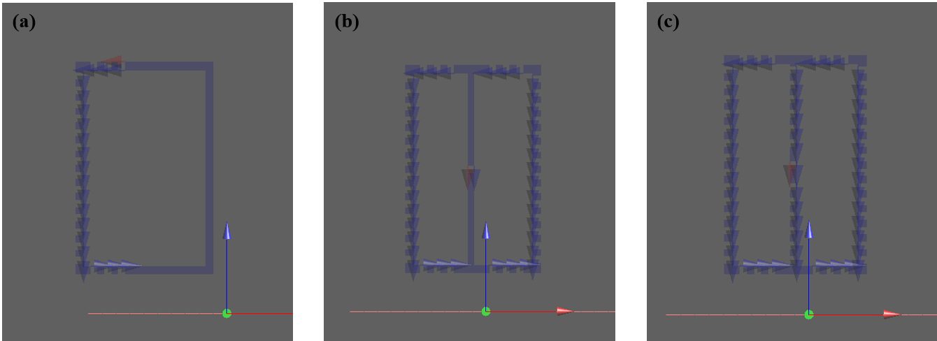
To accommodate spatial B1 inhomogeneity across FOV of a loop coil at 7T clinical scanner and even higher, the asymmetric segmented loop coil (Figure.1 (a)) was proposed at the previous study 1-3. By distributing capacitors on a only half loop, the loop coil generated a more homogenous B1 profile than the coil with symmetrically distributed capacitors over the loop tracer. Generated B1 field strength was, definitely, superior to the strip-line coil 3. However, at the multi channels transceiver array integration; the coils should physically shift to align the non-segmented part of the coil loop on the target. This misalignment might not be applicable on RF coil loop design with various geometry. Accordingly, a versatile RF coil design progressed from the asymmetric segmented loop coil is a requisite for diverse shaped array coil application. In this abstract, a RF coil design is introduced to be able to target ROI with the B1 uniformity and the competitive sensitivity the asymmetric segmented loop coil showed (Figure.1b). It is compared to the coils listed at Figure 1(a, c). The eight channels transceiver phased array with the proposed coil is designed and simulated to research B1 field behavior propagated in a heterogeneous human head model.Methods
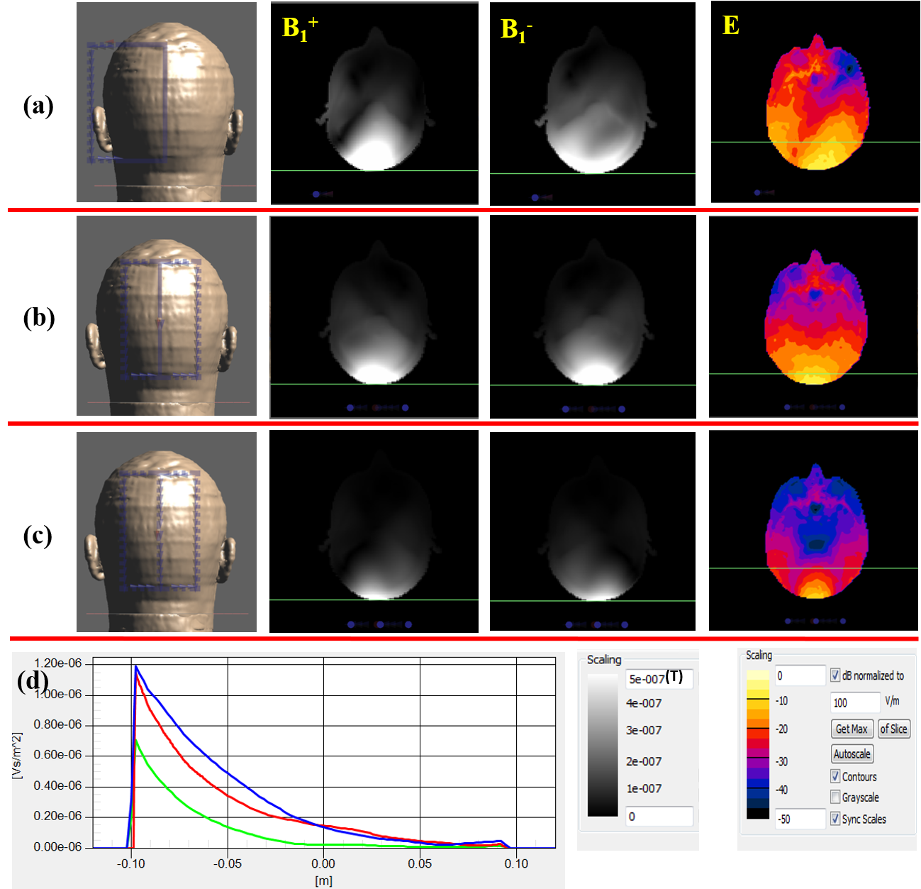
The RF coil introduced in this study is one united two loop coils with asymmetric distributed capacitors such as Figure 1(b). The non-segmented copper tracer was aligned on ROI. It had dimensions of 150mm length and 100mm width with copper tracer of 5mm width and 0.2mm thickness. The coil was tuned at 7T MRI frequency (300MHz). The 50Ω RF source was employed in the middle of the non-segmented copper tracer to generate B1 field disseminated on the numerical head model (Duke, ETH, Zurich, Switzerland). It was calculated by an XFDTD software, SEMCAD X (Ver. 14.8.6 Schmid & Partner Engineering AG, Zürich, Switzerland). It was segmented by twenty places around the loop. By arranging lumped capacitors per segment, the local and global E field generated around the copper tracer, except the middle element, was reduced (Figure 1b). The asymmetric segmented coil and the equally segmented coil on overall coil tracer were prepared for comparative analysis. All three coils, placed under the human occiput with a 20mm gap, were simulated to understand the rotating B1&E field behavior as well as to estimate the coil sensitivity and field uniformity inside the human occiput. After a complete comparison, a volume shaped array coil covering the whole head model of 280mm diameter and 150mm length was created by eight proposed loop coils. The individual channels were arranged with a 15cm gap without the overlap. No decoupling methods were implemented. The configured coil array was investigated by B1 field driven by in phase mode and circular phase mode.Results
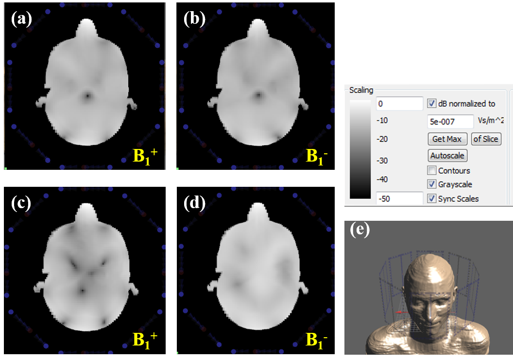
The proposed loop coil created more homogeneous on both B1+&B1- field than the other two coils. Its symmetric E field is also in contrast to the asymmetric segmented loop coil on the desired FOV, shown as Figure 2a-c. It showed 39% and 260% higher B1- profile than the asymmetric segmented loop coil and equally segmented coil on 5cm over the human occiput at the mid-brain axis (Figure 2d). The configured eight channels phased array (Figure 3e) showed the field fading out on in the mid-brain area while driving individual coils with in-phase mode (Figure 3a-b). At CP mode, the shade on mid-brain was resolved and the image distortion by dielectric artifact was minimized (Figure 3d). The minimal shades by the mutual coupling between neighbors coils appeared on the composite image due to no additional decoupling method implementation (Figure 3c-d).Discussion & Conclusion
The RF coil structure merging two loop coils with asymmetric distributed capacitors generated highly homogenous B1 field on the desired FOV in the human head model at 7T MRI. The calculated B1 field uniformity and coil sensitivity of the proposed coil was above the identical sized loop coil with symmetrically distributed capacitance and was competitive to the asymmetric segmented RF coil misaligned on the target. The eight channels phased array loop coil assembly, consisting of the proposed coil loops, was feasible through B1 field simulation study. This design will prospectively help the construction of larger size loop arrays covering more imaging volume at very high fields to obtain both uniform coverage and high sensitivity.Acknowledgements
No acknowledgement found.References
1. Roschmann PK. Radiofrequency penetration and absorption in the human body: Limitations to high-field whole-body nuclear magnetic resonance imaging. Med. Phys. 1987;14:922–31.
2. Vaughan JT, et al. 7T whole body imaging: Preliminary Results. Mag. Reson. Med. 2009;61(1):244-248. 3. Ha SH, et al. Asymmetrically segmented loop phased coil for uniform RF field excitation at 7T. ISMRM 2015;3117.
Figures