4396
Exploring how modeling the head as a multi-layered vs. uniform sphere affects ultimate intrinsic signal-to-noise ratio and coil performance prediction1Center for Advanced Imaging Innovation and Research (CAI2R), Department of Radiology, New York University School of Medicine, New York, NY, United States, 2Bernard and Irene Schwartz Center for Biomedical Imaging, Department of Radiology, New York University School of Medicine, New York, NY, United States, 3Sackler Institute of Graduate Biomedical Sciences, New York University School of Medicine, New York, NY, United States
Synopsis
We investigated differences in ultimate intrinsic SNR and simulated SNR for finite coils when modeling the human head as a single-layer uniform sphere with average brain electrical properties vs. a three-layer sphere that accounts also for skull and skin tissue. We show that the uniform sphere provides a good approximation of the head for simulations up to 3T, but becomes less accurate at ultra-high field strengths.
Introduction
A uniform sphere with average brain electrical properties is typically used to model the human head in ultimate intrinsic signal-to-noise ratio (UISNR) calculations1-4. Recently, Guerin et al.5 explored the difference in UISNR between a uniform sphere and the heterogeneous “Duke” head model6. Their results showed that the overall spatial distribution of the UISNR was similar between the head and the sphere, but at some voxel locations UISNR grew more rapidly with main magnetic field strength (B0) for the realistic head. This suggests that a uniform sphere may not be fully suitable for modeling the head. The goal of this study was to investigate how using a multi-layered sphere mimicking multiple tissues as an intermediate step toward a more realistic head model would affect UISNR results compared to using a uniform sphere.Methods
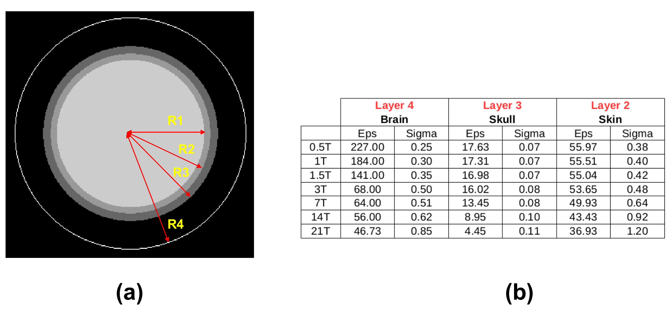
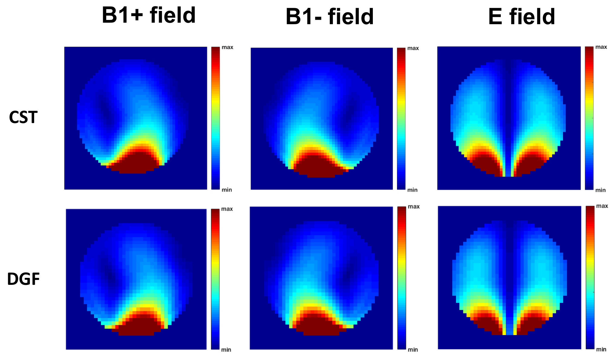
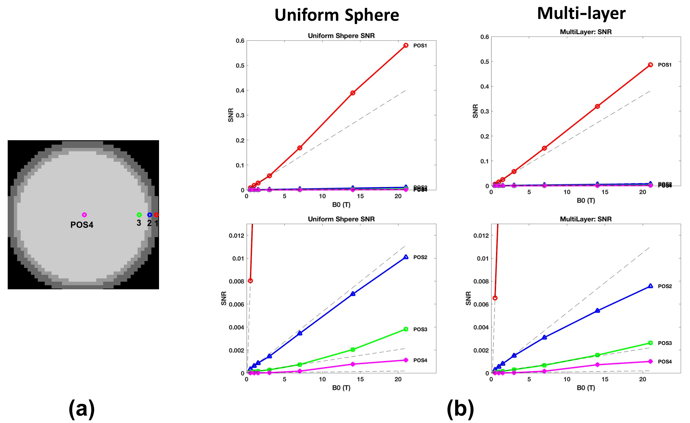
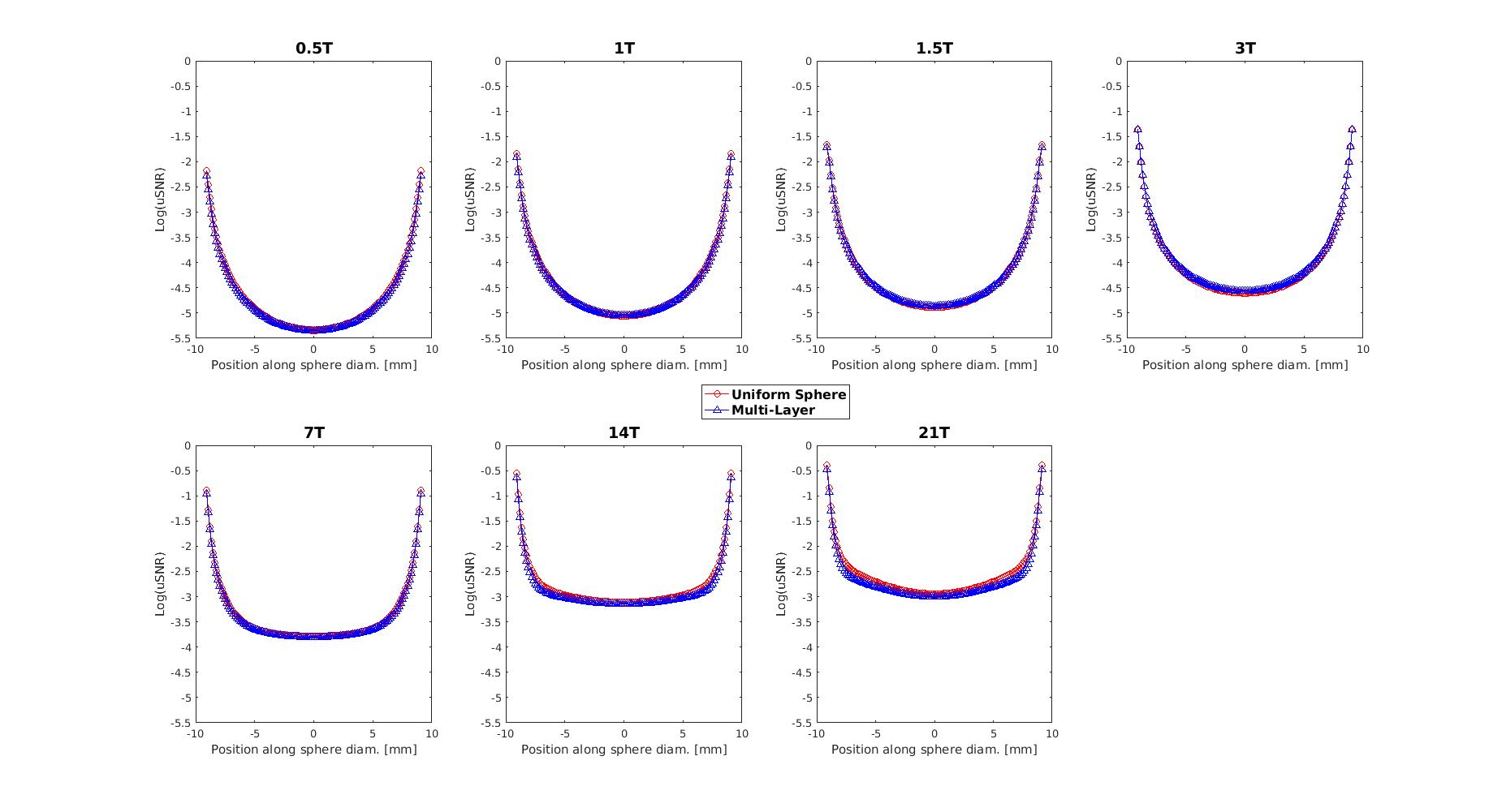
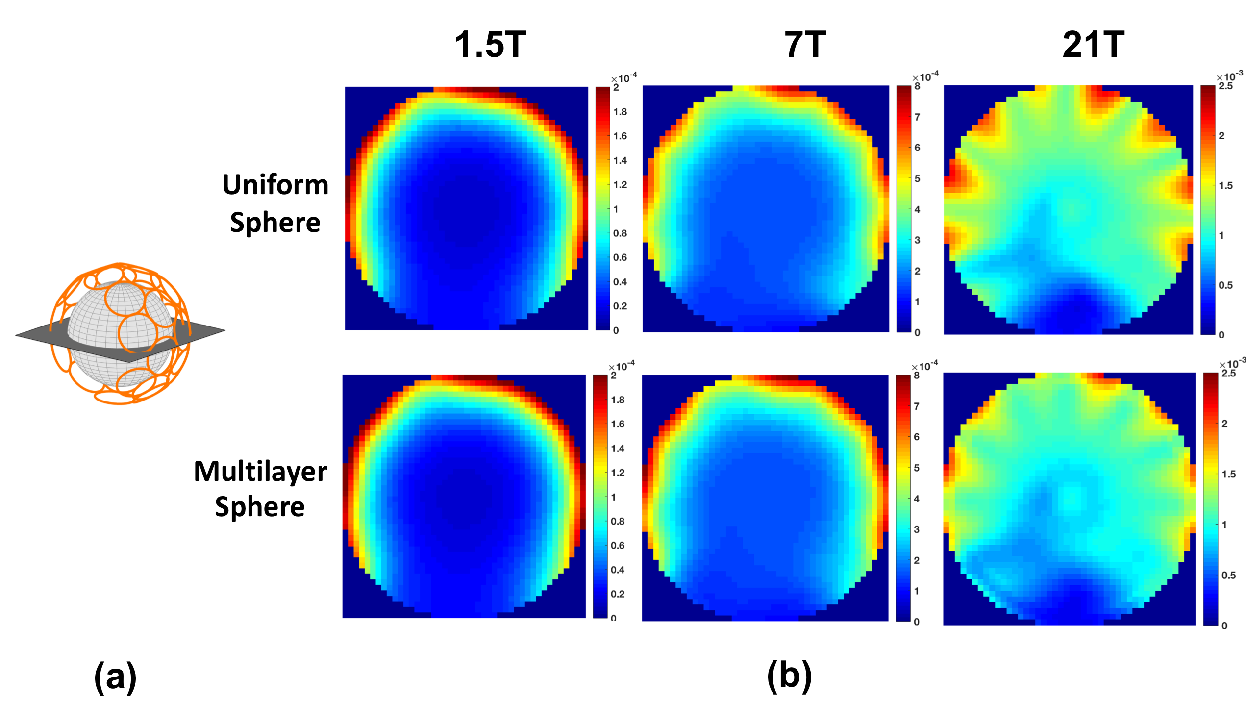
A multi-layered sphere was modeled based on the average geometry of adult brain7 (Figure 1a), including an inner layer with average electrical properties of gray and white matter, and two extra layers mimicking the skull and skin. Electrical properties for each layer at various B0 are obtained from the “Duke” head model and listed in Figure 1b. A uniform sphere was also modeled with radius equal to the largest radius of the multi-layered sphere and average brain electrical properties. We employed a simulation framework based on dyadic Green functions (DGF), which allows to compute analytically the full-wave electromagnetic (EM) field for multi-layered spherical geometries.8-9 We employed a complete basis of current modes, defined on a spherical surface 3 cm away from the object, as receive elements of a hypothetical infinite array, in order to calculate the UISNR2. For validation purposes, we also used an appropriate combination of the basis modes to compute the EM field of a loop coil2 and compared the results with those obtained numerically using CST Microwave Studio 2015 (Computer Simulation Technology, Darmstadt, Germany), for the case of the multi-layered sphere. To evaluate changes in UISNR at different locations similarly to what was done in Ref. 5, we selected 4 voxels at different depth (0.1, 1, 2, 9 cm below the surface of the most outer layer) for both the uniform and the multi-layered sphere (Figure 3a). We also evaluated UISNR along the spheres central diameter for B0 ranging from 0.5T to 21T. Finally, to assess differences between the two head models in a practical setting, we calculated the SNR of a 32-channel helmet array (Figure 5a) for B0 equal to 1.5T, 7T, and 21T.Results
Figure 2 shows that receive (B1-), transmit (B1+), and electric field distribution for the loop coil are spatially consistent between analytic and numerical simulations. This confirms that EM field calculated with the multi-layer DGF simulation framework is accurate. Figure 3a shows that the rate of increase in UISNR for the uniform sphere is higher than that for the multi-layered sphere, especially for the more superficial voxels and ultra-high field, with a peak difference of 45% at 21T. Figure 4 shows UISNR along the sphere diameter is effectively identical between the two models up to 3T, whereas starting from 7T differences appear, mostly in the outer layers. The maximum difference in UISNR between two models increased from 12% at 7T to a maximum of 51% at 21T. Figure 5 also shows minor differences in array SNR between uniform and multi-layered sphere up to 7T, and noticeable differences at 21T.Discussion and Conclusion
Our results suggest that a uniform sphere can be used for modeling the head at low field strengths (B0 < 7T), as the wavelength is long enough to be negligibly affected by the different layers. However, at higher field strengths, a more detailed geometry such as the multi-layered sphere, or a realistic head model5, is needed because the wavelength is short enough that scattering between tissue layers must be taken into accountAcknowledgements
This work was supported in part by NSF 1453675, NIH R01 EB024536 and was performed under the rubric of the Center for Advanced Imaging Innovation and Research (CAI2R, www.cai2r.net), a NIBIB Biomedical Technology Resource Center (NIH P41 EB017183).References
1. Wiesinger F, Boesiger P, Pruessmann KP. Electrodynamics and ultimate SNR in parallel MR imaging. Magn Reson Med 2004;52(2):376-390.
2. Lattanzi R, Sodickson DK. Ideal current patterns yielding optimal signal-to-noise ratio and specific absorption rate in magnetic resonance imaging: computational methods and physical insights. Magn Reson Med 2012;68(1):286-304.
3. Vaidya MV, Sodickson DK, Lattanzi R. Approaching Ultimate Intrinsic SNR in a Uniform Spherical Sample with Finite Arrays of Loop Coils. Concepts Magn Reson Part B Magn Reson Eng 2014;44(3):53-65.
4. Pfrommer A, Henning A. On the Contribution of Curl-Free Current Patterns to the Ultimate Intrinsic Signal-to-Noise Ratio at Ultra-High Field Strength. NMR Biomed 2017;30(5).
5. Guerin B, Villena JF, Polimeridis AG, Adalsteinsson E, Daniel L, White JK, Wald LL. The ultimate signal-to-noise ratio in realistic body models. Magn Reson Med 2017;78(5):1969-1980.
6. Christ A, Kainz W, Hahn EG, Honegger K, Zefferer M, Neufeld E, Rascher W, Janka R, Bautz W, Chen J, Kiefer B, Schmitt P, Hollenbach HP, Shen J, Oberle M, Szczerba D, Kam A, Guag JW, Kuster N. The Virtual Family--development of surface-based anatomical models of two adults and two children for dosimetric simulations. Phys Med Biol 2010;55(2):N23-38.
7. Adeloye A, Kattan KR, Silverman FN. Thickness of the normal skull in the American Blacks and Whites. Am J Phys Anthropol 1975;43(1):23-30.
8. Lattanzi R, Vaidya M, Carluccio G, Sodickson DK and Collins CM. Signal-To-Noise Ratio Gain at 3T Using a Thin Layer of High-Permittivity Material Inside Enclosing Receive Arrays. 22nd Scientific Meeting of the International Society for Magnetic Resonance in Medicine (ISMRM). Milan (Italy), 11-16 May 2014, p. 4814.
9. Li LW, Kooi PS, Leong MS and Yee TS. Electromagnetic dyadic Green's function in spherically multilayered media. IEEE Trans. Microw. Theory Tech. 1994;42(12):2302-2310.
Figures