4390
Exploring the performance of high density detector coil arrays at 10.5 Tesla1Bernard and Irene Schwartz Center for Biomedical Imaging, Department of Radiology, New York University School of Medicine, New York, NY, United States, 2Center for Advanced Imaging Innovation and Research (CAI2R), Department of Radiology, New York University School of Medicine, New York, NY, United States, 3Sackler Institute of Graduate Biomedical Sciences, New York University School of Medicine, New York, NY, United States, 4Center for Magnetic Resonance Research, Department of Radiology, University of Minnesota, Minneapolis, MN, United States
Synopsis
We used a uniform sphere to model the human head and investigated the performance of receive loop arrays for brain imaging at 10.5T to evaluate the advantage of using a large number of detectors, both alone and in combination with high-permittivity materials (HPM). We show that the ultimate intrinsic signal-to-noise ratio in the central region could be approached with a relative small number of loop coils, whereas more elements are needed to maximize SNR near the surface and to achieve large acceleration factors. Superficial SNR at 10.5T could be considerably enhanced using HPM fairly easy to achieve in practice.
Purpose
Previous work showed that the ultimate intrinsic signal-to-noise ratio (UISNR) in head-mimicking spherical objects could be approached using finite arrays of loop coils, with larger number of coils needed as field strength increases1. Many coils at ultra-high field (UHF) strength (B0 ≥ 7T) can also enable large acceleration factors that would not be possible at low field due to intrinsically smaller SNR available with small loops. Furthermore, receive current patterns are less constrained in dense arrays of small loop coils, which means that array elements have the flexibility to act together as large distributed current loops or alone as small loops to maximize SNR at deep or shallow locations, respectively2. Superficial SNR could be further improved by placing high-permittivity materials (HPM) near the array elements3-5. The aim of this work is to investigate the performance of receive loop arrays at 10.5T to evaluate the advantage of using many detectors, both alone and in combination with HPM.Theory and Methods
We employed a dyadic
Green’s function (DGF) framework for multi-layered spherical geometries5,6,
which enables the expression of any current distribution as a weighted
combination of the elements of a complete basis of current modes, defined on a
spherical surface at a fixed distance from the object. We modeled a 9cm radius
uniform sphere with average brain electrical properties at 10.5T (Fig. 1) and we defined the current
distribution on a concentric spherical surface with 11cm radius. We employed 8,712
current modes, equally divided in curl-free and divergence-free types2,
as elements of a hypothetical infinite array to calculate the UISNR2
for a central transverse plane. We also calculated the corresponding SNR for
two helmet-like close-fitting arrays with 64 and 96 loops (Fig. 2a), as well as for enclosing loop arrays with 32, 64 and 96
symmetrically packed elements (Fig. 3a).
For the enclosing set we evaluated the SNR also in the presence of a continuous
layer of HPM with thickness = 1cm, σ = 0 and εr = 100 and 300, which
was modeled under the coil elements (Fig.
1). Coil noise was included in array SNR calculations.Results and Discussion
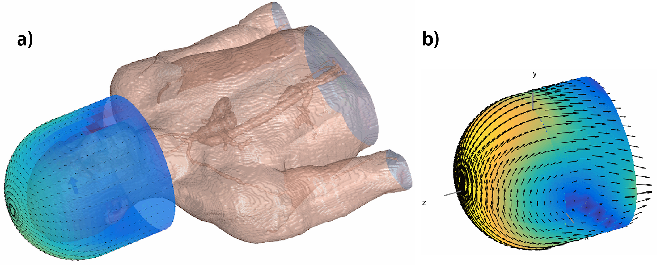
Fig. 2.b shows that at 10.5T both 64- and 96-element helmet-like arrays can capture most of the available SNR at the center. However, more elements enable larger acceleration factors with lower noise amplifications, as shown by the inverse g-factor maps in Fig. 2.c. While 32 coils arranged around the sphere can already saturate central UISNR, more and smaller coil elements can improve absolute array performance near the surface (Figs. 3.b and 4.a). Since the number of coils that can be packed in a head array is necessarily limited by practical constraints, an alternative approach to improve superficial SNR is adding a layer of HPM (Figs. 3.c,d and 4.b,c). Using HPM with εr = 100 did not affect central SNR, but changed the performance near the surface (Fig. 3.d). In particular, the larger the number of coils in the array, the more uniform and extended was the region associated with a gain in SNR. While using HPM with εr = 300 (Fig. 3.d) could boost array performance near the surface, e.g., in the cerebral cortex, for all cases (+200%, +230%, +130% for 32, 64 and 96 coils, respectively), it could also considerably reduce SNR at the center, especially for small arrays (-56%, -25%, -8% for 32, 64 and 96 coils, respectively). While a limitation of this work is the approximation of the human head with a uniform sphere, recent work using a realistic human head model showed that the UISNR behavior for a central transverse plane is very similar to the case of the uniform sphere7, suggesting that our results are generalizable. Furthermore, it has been shown that optimal array design depends mostly on the surface where the coils are arranged, rather than the object geometry8. For example, Fig. 5 shows that using a dome-like coil substrate, the signal-optimal current patterns, which at UHF are expected to maximize also SNR8, follow closed trajectories on the hemispherical cap and a chevron pattern dominated by z-directed currents on the inferior cylindrical portion. This suggests that optimal array design for 10.5T head imaging may require combining loops and dipoles9-11.Conclusion
Central UISNR in a brain-mimicking sphere could be approached at 10.5T with finite arrays. The larger the number of loops the smaller the g-factor and the higher the SNR gain achievable with HPM. Ongoing work will include simulations with a realistic head model and combinations of loop and dipole elements, leading to the construction of a high-density detector array with integrated HPM.Acknowledgements
This work was supported in part by NIH U01 EB025144, NIH R01 EB024536, NIH S10 RR029672, NSF 1453675, and was performed under the rubric of the Center for Advanced Imaging Innovation and Research (CAI2R, www.cai2r.net) and CMRR, NIBIB Biomedical Technology Resource Centers (NIH P41 EB017183 and P41 EB015894).References
1. Vaidya M, Sodickson DK and Lattanzi R. Approaching ultimate intrinsic SNR in a uniform spherical sample with finite arrays of loops coils; Concepts in Magnetic Resonance. Part B, Magnetic Resonance Engineering. 2014;44(3):53-65.
2. Lattanzi R and Sodickson DK. Ideal current patterns yielding optimal SNR and SAR in magnetic resonance imaging: computational methods and physical insights; Magnetic Resonance in Medicine. 2012;68(1):286-304.
3. Webb AG. Dielectric Materials in Magnetic Resonance. Concept Magn Reson A. 2011;38A(4):148-184.
4. Yang QX, Rupprecht S, Luo W, Sica C, Herse Z, Wang J, Cao Z, Vesek J, Lanagan MT, Carluccio, G, Ryu YC and Collins CM. Radiofrequency field enhancement with high dielectric constant (HDC) pads in a receive array coil at 3.0T. J Magn Reson Imaging. 2013;38(2):435-440.
5. Lattanzi R, Vaidya M, Carluccio G, Sodickson DK and Collins CM. Signal-To-Noise Ratio Gain at 3T Using a Thin Layer of High-Permittivity Material Inside Enclosing Receive Arrays. 22nd Scientific Meeting of the International Society for Magnetic Resonance in Medicine (ISMRM). Milan (Italy), 11-16 May 2014, p. 4814.
6. Li LW, Kooi PS, Leong MS and Yee TS. Electromagnetic dyadic Green's function in spherically multilayered media. IEEE Trans. Microw. Theory Tech. 1994;42(12):2302-2310.
7. Guérin B, Villena JF, Polimeridis AG, Adalsteinsson E, Daniel L, White JK and Wald LL. The ultimate signal-to-noise ratio in realistic body models. Magn Reson Med. 2017;78(5):1969-1980.
8. Sodickson DK, Lattanzi R, Vaidya M, Chen G, Novikov D, Collins C and Wiggins GC, The Optimality Principle for MR Signal Excitation and Reception: New Physical Insights Into Ideal RF Coil Design. 25th Scientific Meeting of the International Society for Magnetic Resonance in Medicine (ISMRM). Honolulu (HI), 22-27 April 2017, p. 756
9. Woo MK, Lagore R, DelaBarre L, Lee B, Yigitcan E, Radder J, Ertruk A, Metzger G, Van de Moortele PF, Ugurbil K and Adriany G, A Geometrically Adjustable Loop-Dipole (LD) Head Array for 10.5T. 25th Scientific Meeting of the International Society for Magnetic Resonance in Medicine (ISMRM). Honolulu (HI), 22-27 April 2017, p. 1051.
10. Wiggins GC, Zhang B, Cloos MA, Lattanzi R. Chen G, Lakshmanan K, Haemer G and Sodickson DK. Mixing loops and electric dipole antennas for increased sensitivity at 7 Tesla. 21st Scientific Meeting of the International Society for Magnetic Resonance in Medicine (ISMRM). Salt Lake City (UT), 20-26 May 2013, p. 2737.
11. Lattanzi R, Wiggins GC, Zhang B, Duan Q, Brown R and Sodickson DK. Approaching ultimate intrinsic signal-to-noise ratio with loop and dipole antennas. Magnetic Resonance in Medicine. 2017; in press.
12. Vaidya MV, Deniz CM, Collins CM, Sodickson DK and Lattanzi R, Manipulating transmit and receive sensitivities of radiofrequency surface coils using shielded and unshielded high-permittivity materials. MAGMA. 2017; in press.
Figures