4316
Development of Multi-Coil B0 Technology with Computer-Aided Design Software1Department of Biomedical Engineering, Columbia University in the City of New York, New York, NY, United States, 2Department of Radiology, Columbia University in the City of New York, New York, NY, United States
Synopsis
The multi-coil (MC) technique proved to enable both B0 shimming and spatial encoding for MRI. However, to eventually establish this technology for clinical use in human subjects, it has to evolve from a proof of concept level to a professional stage. Here we present the use of computer aided design (CAD) software to overcome increased engineering challenges that are associated with complex coil geometries and larger coil currents. A customized Add-in for SolidWorks was created to convert MC designs from the text-based Public MC Information Policy format to full CAD representations and vice versa, thereby providing improved field modeling and engineering capabilities.
Introduction
Traditionally, B0 manipulations needed in MRI both for B0 shimming and imaging are done by dedicated coils with specific geometries targeting specialized field distributions. Lately, the multi-coil (MC) technique has been introduced replacing those coils with an array of smaller individually driven coils, whose combined fields can produce the desired target fields. This approach has been successfully used both in a static and a dynamic (Dynamic Multi-Coil Technique or DYNAMITE) fashion for B0 shimming of in rodents1,2 and humans3,4,5. Moreover, it has been demonstrated that the MC technique can also be used to create the gradient fields necessary for MR imaging6,7, potentially rendering the presence of traditional gradient coils obsolete.
With a growing MC community and an increasing number of related publications, it becomes increasingly important to ensure reproducibility and rigor, for which the Public Multi-Coil Information (PUMCIN) policy has been proposed8. Still, to date, DYNAMITE is only applied in a few specialized MR research laboratories worldwide. More importantly, the design and construction of MC setups has to evolve from a proof-of-concept to a professional stage to further disseminate the technology and eventually establish it for clinical use. The application of DYNAMITE for human imaging demands larger coils and higher coil currents as well as close integration with the RF coil and the magnet9. The engineering challenges therefore progressively resemble those of conventional gradient coil designs including the accurate consideration of mechanical forces, heat generation and electromagnetic interactions (e.g. eddy currents).
Here we present the application of a newly established integrated MC processing and CAD engineering environment for the preliminary design and optimization of 31-element MC array tailored to imaging the human brain in the world’s first head-only 1.5 T scanner (NIH-NIBIB, U01 EB025153, PI: M. Garwood, UMN).
Methods
To date, the design of MC technology in our laboratory has been based on Biot-Savart simulations of simplified coil geometries using customized MATLAB (MathWorks) software (B0DETOX2). To make use of the capabilities of modern CAD software, a custom Add-in was written for SolidWorks (Dassault Systèmes) that is capable of importing and exporting MC wire patterns stored in the PUMCIN file format8. This way, complex coil shapes can be created in SolidWorks and their B0 field modeling capability can be analyzed in MATLAB. Similarly, existing MC designs developed in MATLAB can be used as basis for full CAD realization including crucial engineering aspects such as heat dissipation or mechanical stability. The achieved full forward and backward capability between CAD and the MC simulation environment furthermore enables the use of SolidWorks’ finite element analysis capabilities. The Add-in is fully integrated into the SolidWorks user interface, very user friendly and publicly available for download10.
Results
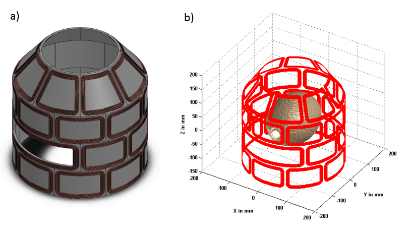
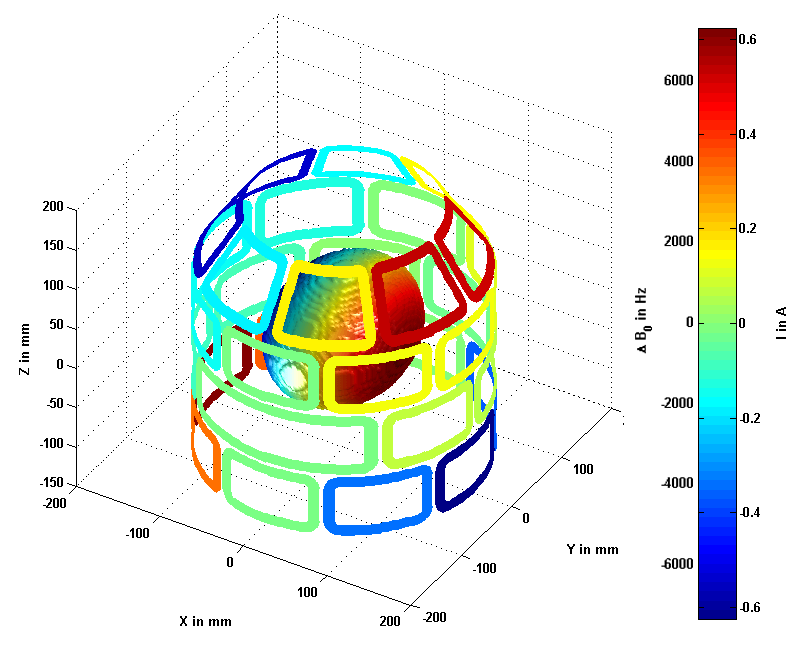
A 31-coil MC setup was first developed in our MATLAB based simulation environment based on approximate dimensions of the head-only scanner (not shown) and subsequently adapted in SolidWorks to consider practical aspects of the MC design as well as mounting structures and space limitations (Fig. 1a). The CAD wire paths were then exported to a text file with the custom-made Add-in for further analysis of the true MC setup with B0DETOX (Fig. 1b). Here, the MC current distribution for the generation of an exemplary 1 kHz/cm X gradient field in an elliptical region-of-interest (15x20x15 cm) is shown (Fig. 2).
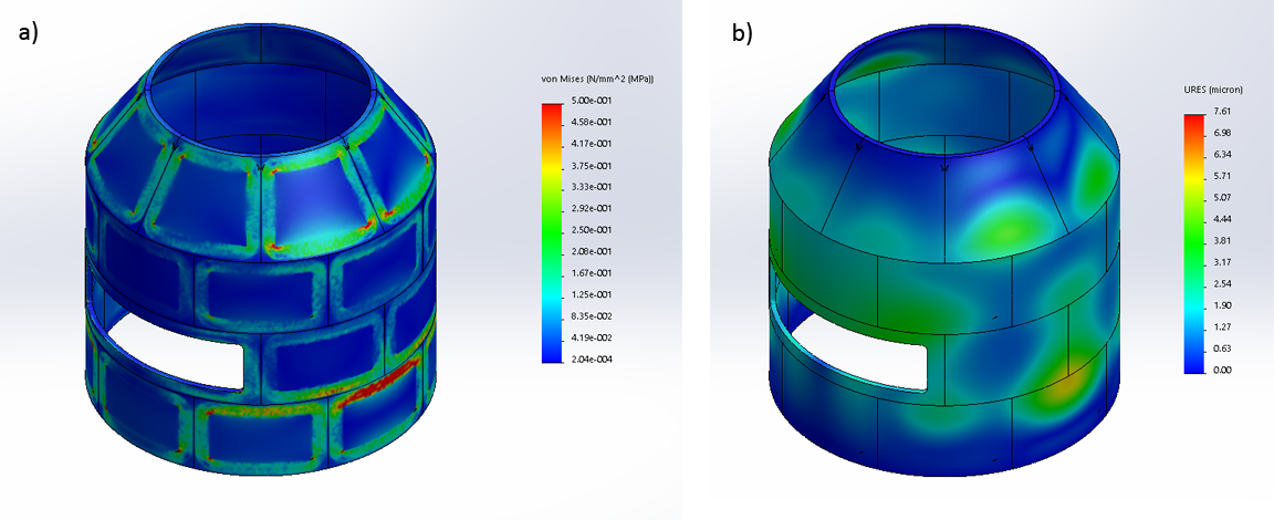
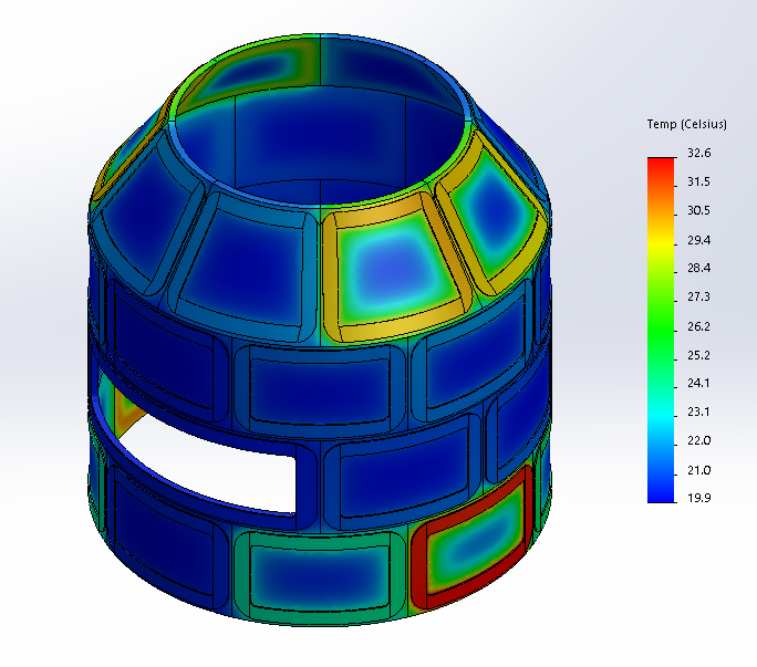
Based on the derived currents, the distribution of Lorentz forces acting on the individual coils were predicted for the 1.5 T scanner B0 field. The SolidWorks design and the calculated forces were then used to simulate the mechanical stress acting on the MC setup during the gradient generation (SolidWorks Simulation, Fig. 3). Additionally, the heat dissipation from each of the coils was calculated and the temperature distribution in the MC design simulated assuming convectional cooling (Fig. 4).
Conclusion & Outlook
The preliminary results presented here show the potential of an integrated software environment comprising dedicated MC and CAD software for the design of advanced MC setups. Future extensions will consider further experimental details (e.g. materials, mounting, machinability) and take advantage of the full CAD capabilities to refine the modeling of realistic conditions (e.g. heat behavior at limited or no convection, water cooling).
To date, most MC geometries were arranged on regular cylindrical or elliptical surfaces. The use of CAD software is expected to be particularly beneficial for the design and construction of irregular MC geometries targeting the human head, torso, or specialized solutions e.g. for extremities.
Mechanical, thermal, electromagnetic and MC simulations will first be used for the realization of the novel MC-based gradient concept for head-only MRI at 1.5 T. More importantly, this integrated computational environment is expected to set the stage for improved design and engineering of MC hardware in the future.
Acknowledgements
This research was supported by NIH grant U01 EB025153.References
1. Juchem C, Brown PB, Nixon TW, McIntyre S, Rothman DL, De Graaf RA. Multicoil shimming of the mouse brain. Magn Reson Med. 2011;66(3):893-900.
2. Juchem C, Herman P, Sanganahalli BG, et al. DYNAmic Multi-coIl TEchnique (DYNAMITE) shimming of the rat brain at 11.7T. NMR Biomed. 2014;27(8):897-906.
3. Juchem C, Nixon TW, McIntyre S, Boer VO, Rothman DL, de Graaf RA. Dynamic multi-coil shimming of the human brain at 7 T. J Magn Reson. 2011;212(2):280-288.
4. Stockmann JP, Witzel T, Keil B, et al. A 32-channel combined RF and B0 shim array for 3T brain imaging. Magn Reson Med. 2016;75(1):441-451.
5. Topfer R, Starewicz P, Lo K-M, et al. A 24-channel shim array for the human spinal cord: Design, evaluation, and application. Magn Reson Med. 2016;76(5):1604-1611.
6. Juchem C, Nixon TW, McIntyre S, Rothman DL, de Graaf RA. Magnetic field modeling with a set of individual localized coils. J Magn Reson. 2010;204(2):281-289.
7. Juchem C, Nahhass OM, Nixon TW, de Graaf RA. Multi-slice MRI with the dynamic multi-coil technique. NMR Biomed. 2015;28(11):1526-1534.
8. Juchem C, de Graaf RA. The public multi-coil information (PUMCIN) policy. Magn Reson Med. 2017;78:2042-2047.
9. Garwood M, Adriany G, DelaBarre L, et al. Methods for Magnetic Resonance Imaging with Multi-Coil Array Steering of Resonance Through Space. Provisional Patent Application, US 62/482.299; 2017.
10. Theilenberg S, Juchem C. SolidWorks PUMCIN Add-in. http://juchem.bme.columbia.edu.
Figures