4314
Improved Transmit Field Homogeneity in Simultaneous EEG-fMRI at 7T by Increasing EEG Wire Resistance1Laboratory of Functional and Metabolic Imaging, École polytechnique fédérale de Lausanne (EPFL), Lausanne, Switzerland, 2Center for Biomedical Imaging - Animal Imaging and Technology, École polytechnique fédérale de Lausanne (EPFL), Lausanne, Switzerland, 3Department of Radiology, University of Geneva, Geneva, Switzerland, 4Department of Radiology, University of Lausanne, Lausanne, Switzerland
Synopsis
Simultaneous EEG-fMRI offers rich multimodal information of brain activity. However, data quality is adversely affected by mutual interactions. Especially at higher magnetic fields, conductive scalp EEG components cause substantial transmit field disruption.
Here, electromagnetic field simulations and MR measurements at 7T performed on a realistic design of the wiring of a 64-channel EEG cap showed that transmit field attenuation and inhomogeneity are significantly reduced when wires are split into smaller lengths by resistors, suggesting a cancellation of resonant antenna effects. This offers an effective and practical solution to avoid EEG-induced MRI data degradation, maximizing the sensitivity benefits available at 7T.
Introduction
In simultaneous electroencephalography and functional magnetic resonance imaging (EEG-fMRI), radio frequency (RF) fields can be shielded by conductive scalp EEG components densely surrounding the human head.1 At 7T, this leads to strong attenuation of the transmit field (B1+) within the imaging subject2, producing significant signal losses, and compromising the functional sensitivity boosts achievable at this field strength.1,3
Using electromagnetic field simulations and MR measurements at 7T, the aims of this study were to assess the B1+ shielding caused by a 64 channel EEG cap and to evaluate how the MR compatibility of the EEG cap is improved in terms of B1+ homogeneity when the wires are split with 1kΩ resistors.
Methods
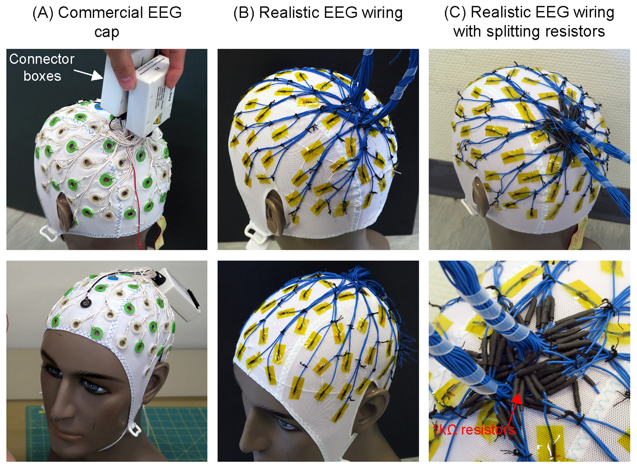
MR acquisitions were conducted with a 7T head-only scanner (Siemens, Germany) and an 8-loop volume head array (Rapid Biomedical, Germany). B1+ amplitude was mapped in the following setups (Fig.1) using SA2RAGE4:
- A) Commercial EEG cap with 64 channels (EasyCap, Germany), Ag/AgCl electrodes and short EEG wires (10-30cm) terminating in two connector boxes. 5kΩ current limiting resistors are located at both ends of each wire. Scalp-electrode impedance was reduced using electrolyte gel.
- B) Realistic EEG wiring was mimicked with 64 copper wires placed with similar geometry to the commercial cap.
- C) Realistic EEG wiring with 1kΩ splitting resistors. Non-magnetic resistors (Vishay, USA) are soldered to each wire, resulting in segments shorter than 15cm.
Measurements with the commercial EEG cap were performed on a human volunteer in a previous study.3 Those with the EEG wiring were performed on a head-shaped agar-gel phantom.
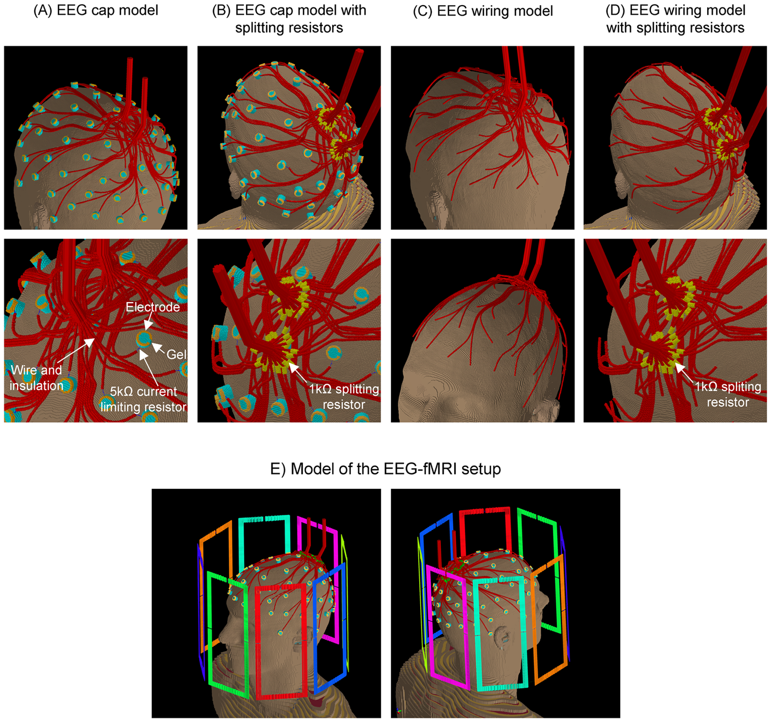
Finite Difference Time Method (FDTD) simulations were performed on the realistic human model Duke (Virtual Family5) using Sim4Life 3.2.4.1836 (ZMT, Switzerland) to compute B1+ maps. The volume coil (Fig.2E) was modeled as stripes of perfect electric conductors with adjusted capacitors and sources providing a circularly polarized excitation at 297.2MHz. The following simulation models (Fig.2) were built:
- A) EEG cap model built as close as possible to reality: open-ring electrodes and wires were modeled as perfect electric conductors with 5kΩ current-limiting resistors in-between. Wires were individually routed towards the connectors located 9cm above the scalp. Dielectric cylinders mimicked the electrolyte gel used in experiments.
- B) EEG cap model with 1kΩ splitting resistors added to each wire of model A.
- C) EEG wiring model, with only wires from model A.
- D) EEG wiring model with 1kΩ splitting resistors added to wires of model C.
Models were voxelized in 141.9MCells with non-uniform grid steps from 0.23×0.24×0.26mm3 to 65×65×69mm3. Steady-state conditions (convergence level 50dB) were achieved within 100 periods of simulation time.
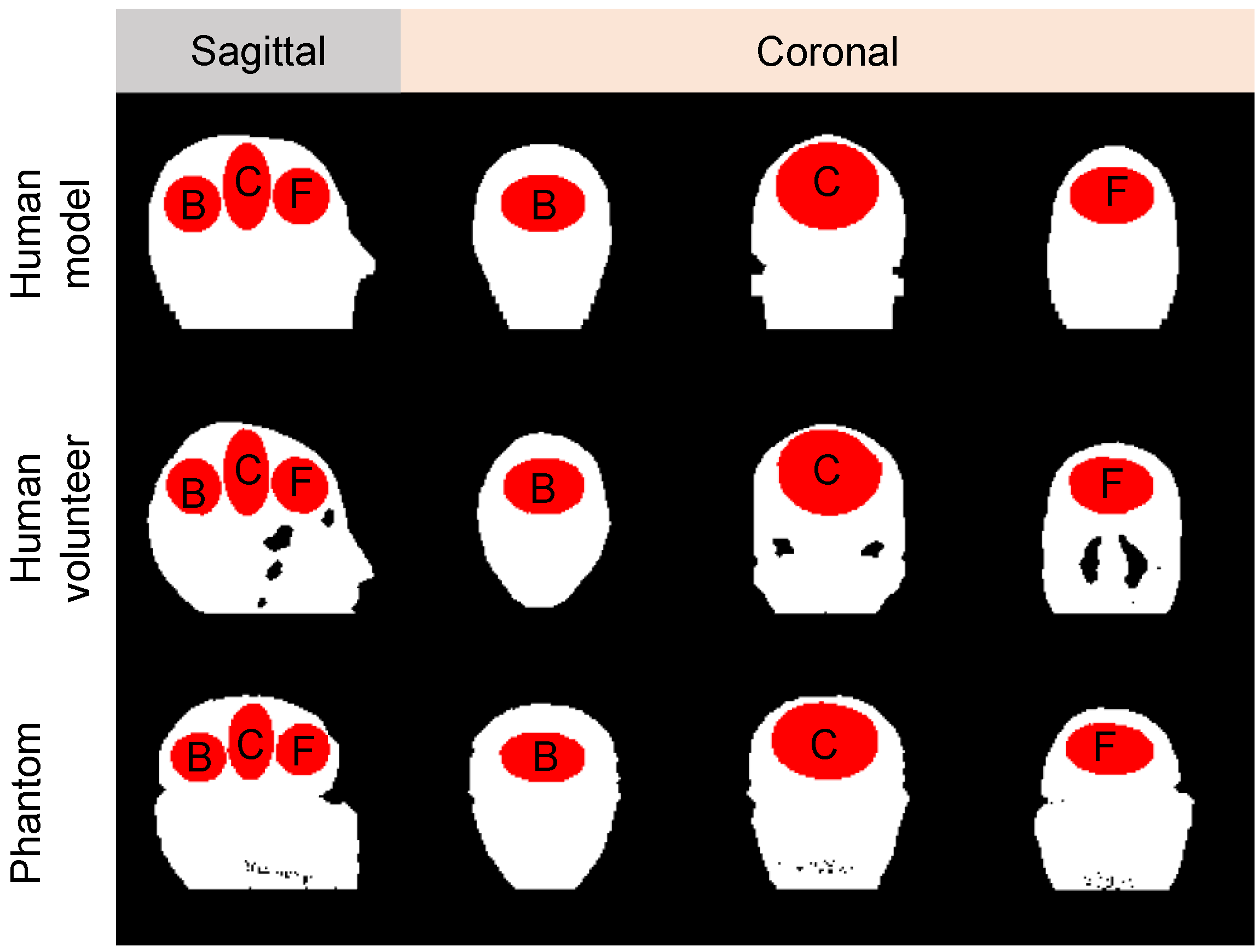
For comparison across the different tested configurations in both measurements and simulations, B1+ amplitude was averaged within the whole imaging subject as well as ellipsoidal regions (Fig.3).
Results
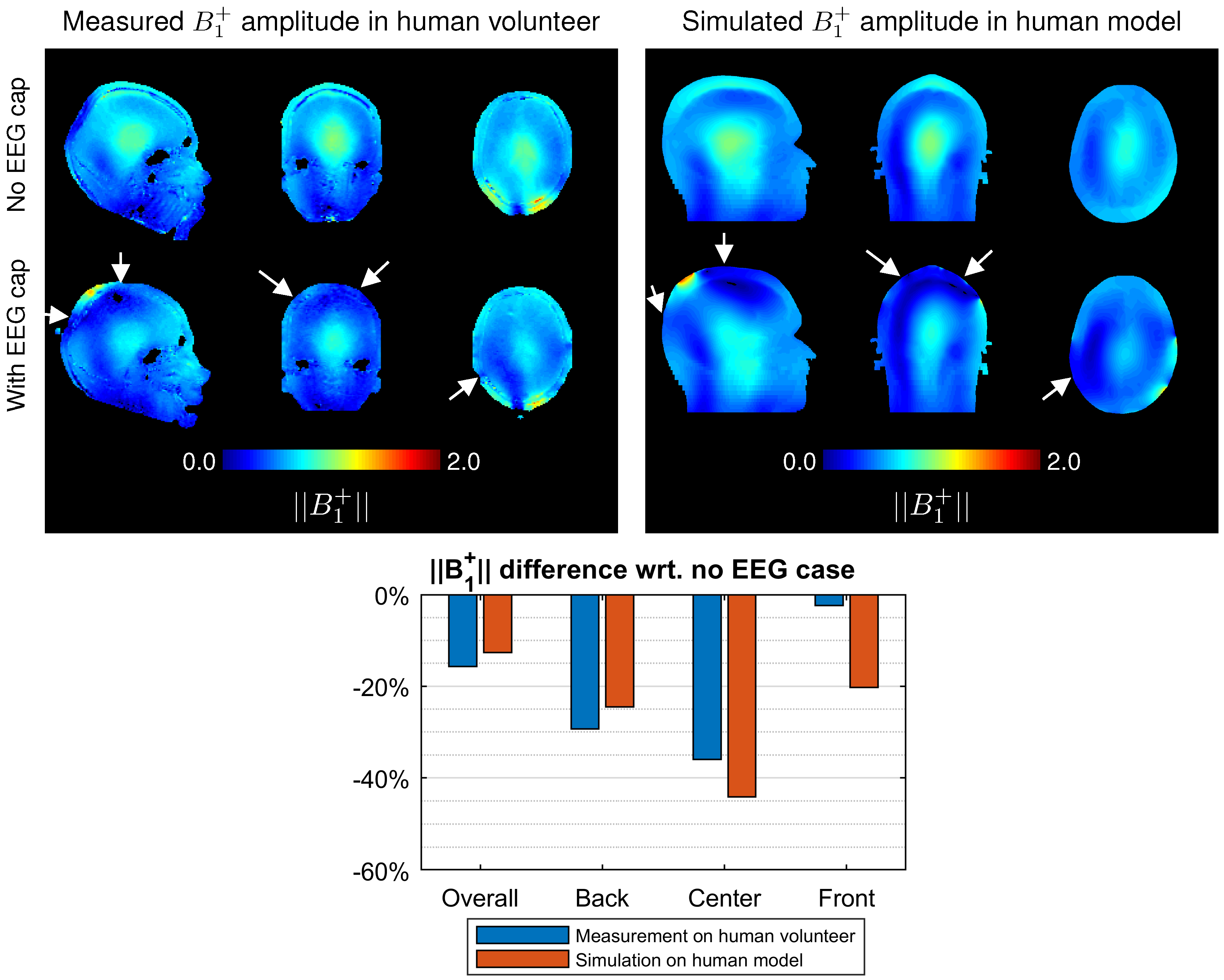
In measurements and simulations, the EEG cap leads to B1+ attenuation by 16% and 13%, respectively in overall, and by 36% and 44%, respectively at the center (Fig.4). Strong attenuation was observed at the back and center of imaging subjects (Fig.4, arrows). Results of measurements and simulations were in general agreement, except for the stronger attenuation at the front of the head in simulations.
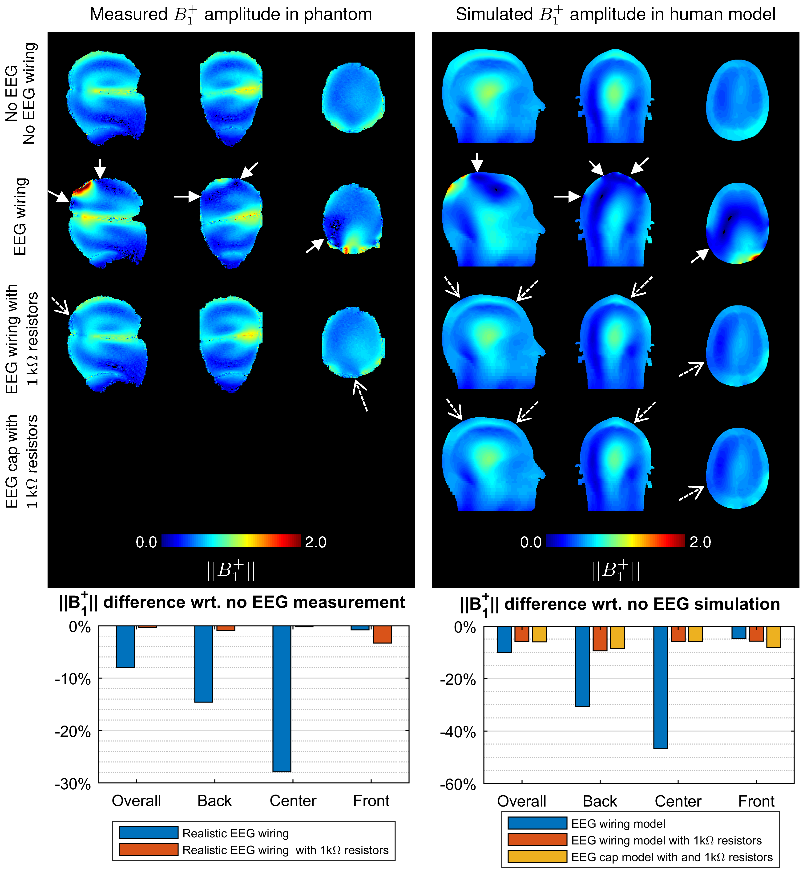
The EEG wiring caused strong B1+ attenuation comparable to the EEG cap (Fig.5, solid arrows). Notably, splitting the wires with resistors canceled most of the strongly attenuated regions, with only a few regions with slight attenuation remaining close to the scalp (Fig.5, dotted arrows). At the center, the attenuation decreased from 28% to 0% in measurements and from 47% to 6% in simulations. Similar improvements were observed in the EEG cap model with splitting resistors. The added resistors did not cause supplementary static field inhomogeneity in MR measurements.
Discussion and Conclusion
In this study, FDTD simulations and MR measurements showed that the EEG cap wiring causes strong B1+ attenuation and inhomogeneity for MRI at 7T. Splitting the wires with 1kΩ resistors appeared to be an effective and practical solution to reduce B1+ attenuation and inhomogeneity.
1kΩ resistors provide an adequate compromise to reduce the coupling of the wires to the RF coil and avoid increasing significantly the EEG signal noise, since the EEG channel impedance only increases by 10%. RF-induced standing waves were found to be building-up within wires having a length between 20 and 30cm (results not shown here). Hence, only these resonating wires need to be split in order to reduce B1+ disruption and improve the compatibility of the EEG cap with 7T scanners.
Therefore, this is a highly promising approach to avoid EEG-induced MRI data degradation, and fully benefit from the functional sensitivity boosts achievable at 7T.
Acknowledgements
This study was supported by the Centre d’Imagerie Biomédicale (CIBM) of the Université de Lausanne (UNIL), the Université de Genève (UNIGE), the Hôpitaux Universitaires de Genève (HUG), the Centre Hospitalier Universitaire Vaudois (CHUV), the École Polytechnique Fédérale de Lausanne (EPFL), the Fondation Leenaards and the Fondation Louis-Jeantet.References
1. Mullinger K, and Richard B. Influence of EEG Equipment on MR Image Quality. in Simultaneous EEG and fMRI: Recording, Analysis, and Application. Oxford University Press. 2010
2. Ipek Ö, Jorge J, Grouiller F, et al. RF safety assessment of simultaneous EEG-fMRI at 7T MR, Proc. ISMRM 23 (2015), 1864
3. Jorge J, Grouiller F, Ipek Ö, et al. Simultaneous EEG–fMRI at ultra-high field: Artifact prevention and safety assessment. NeuroImage. 105 (2015) 132–144
4. Eggenschwiler F, Kober T, Magill AW, et al. SA2RAGE: a new sequence for fast B1+-mapping. Magn Reson Med. 2012 Jun;67(6):1609-19
5. Gosselin MC, Neufeld E, Moser H et al. Development of a new generation of high-resolution anatomical models for medical device evaluation: the Virtual Population 3.0. Physics in Medicine and Biology, 59(18):5287, 2014.
Figures