4313
B1 vector field mapping through multi-orientation B1+ measurements1Department of Biomedical Engineering, Sungkyunkwan University, Suwon, Republic of Korea, 2IBS Center for Neuroscience Imaging Research, Suwon, Republic of Korea, 3Bioimaging Research Team, Korea Basic Science Institute, Cheongju, Republic of Korea
Synopsis
We present theory and experimental validation of reconstruction of all three components of RF vector magnetic field (B1 vector) in MRI. Using eight-orientation B1+ magnitude mapping, the magnitudes and relative phases of all Cartesian components of B1 vector can be unambiguously determined. The method is demonstrated on a phantom in a birdcage transmit coil with a standard B1+ mapping sequence at 3T. Our method can be used to validate assumptions in MR-based electrical properties tomography (MR-EPT) and specific absorption rate (SAR) modeling.
Introduction
Increased tissue-RF field interactions at ultra-high-field MRI presents challenges in two ways: image shading and tissue heating. While the former involves only one (proton co-rotating) component of the RF field ($$$B_1^+$$$), heating is contributed by all three components of the RF vector magnetic field (B1 vector) through induction of an electric field. Experimental measurement of the B1 vector field is therefore relevant to modeling specific absorption rate (SAR) in high-field MRI. Also, MR-based electrical properties tomography (MR-EPT)1,2 could benefit from additional B1 field information. While conventional B1 mapping only measures $$$B_1^+$$$, Florian et al.3 noted in 2006 that other B1 components could be accessed by multi-orientation measurements. Here, we present a theory of B1 vector field mapping from multi-orientation scans, and provide experimental validation through phantom measurements and RF field simulations.Theory
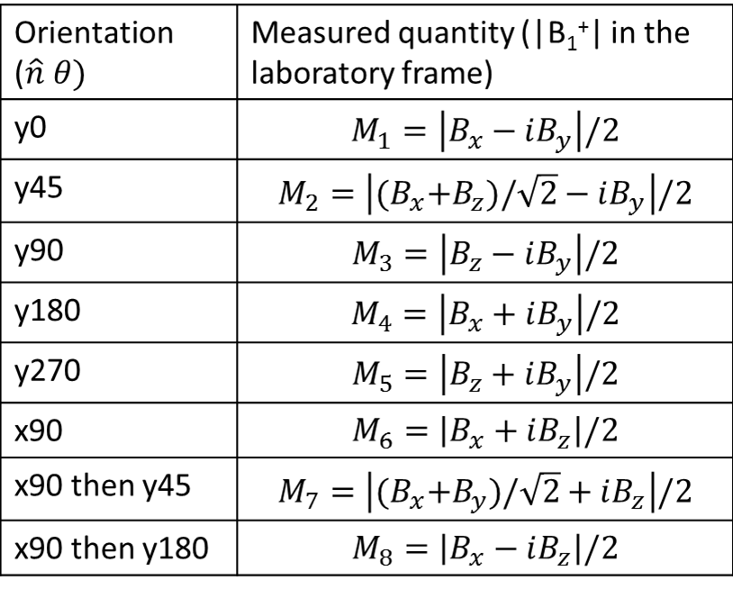
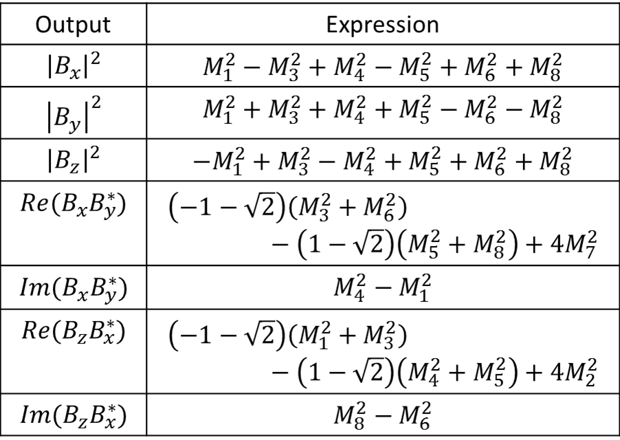
We will assume that the RF transmitter is small enough compared to the scanner’s RF shield that the B1 field of interest is not significantly affected by the shield. Accordingly, we define an “RF system” as the transmitter and the object being scanned with their relative positions fixed. We aim at finding the B1 components $$$(B_x, B_y, B_z)$$$ in the RF system before rotation. Conventional $$$B_1^+$$$ mapping only measures $$$B_{1,orig}^+ = |B_x – iB_y|/2$$$. If we now rotate the RF system by ϑ around an axis $$$\hat{n} = (n_x,n_y,n_z)$$$, the B1 vector in the magnet’s reference frame becomes $$$\vec{B}_{1new} = R(\hat{n},\theta) \vec{B}_{1orig}$$$, where $$$R$$$ is a rotation matrix. The corresponding new, measureable $$$B_1^+$$$ magnitude is given by $$ |B_{1,new}^+|=|(\cos\theta-in_z\sin\theta)(B_x-iB_y) +B_z(n_y+in_x)\sin\theta + \vec{B}\cdot\hat{n}(n_x-in_y)(1-\cos\theta)|.$$ Multiple-orientation measurements of the above quantity can allow disentangling of magnitudes and relative phases of $$$(B_x, B_y, B_z)$$$. Many multi-orientation strategies can be devised, balancing mathematical complexity and experimental practicality. Here we present an 8-orientation method which involves large angles but allows mathematically straightforward solution. The relevant equations are summarized in Tables 1-2.Methods
Experiment
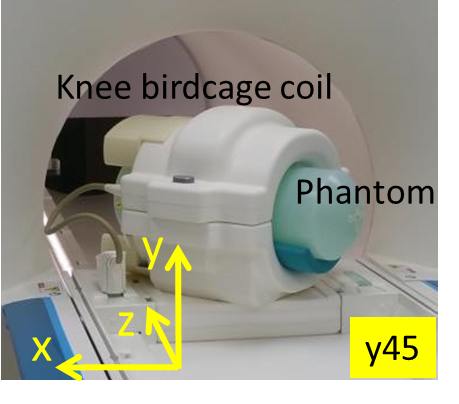
$$$B_1^+$$$ maps on a cylindrical phantom were acquired in a 3T whole-body scanner (Magnetom Prisma, Siemens Healthineers, Germany) with a vendor-provided extremity (knee) coil, consisting of 1 quadrature (birdcage) transmit coil and 15 receive elements. A vendor-provided fast $$$B_1^+$$$ mapping sequence4 was applied to each of the eight orientations to produce a set of 2D $$$B_1^+$$$ maps on the phantom’s axial plane. During prescription, scan planes were rotated to follow the phantom orientation. The phantom was a cylinder with length (flat part) = 42 cm and diameter = 14.4 cm, consisting of aqueous solution of NaCl and NiSO4, as provided by the vendor. The acquired $$$B_1^+$$$ maps were processed according to Tables 1-2 to calculate the magnitudes and relative phases of the RF-frame components of B1.
Simulation
The RF fields were simulated in XFdtd v7.6 (Remcom, USA) on the following model: high-pass birdcage coil with 12 rungs, diameter/length = 20/20 cm, frequency = 123.25 MHz; an axially located cylindrical phantom with σ=1 S/m, εr=78, length/diameter = 42/14.4 cm. The effect of an RF shield was tested and found to affect B1 field by less than 4% at tested orientations.
Results
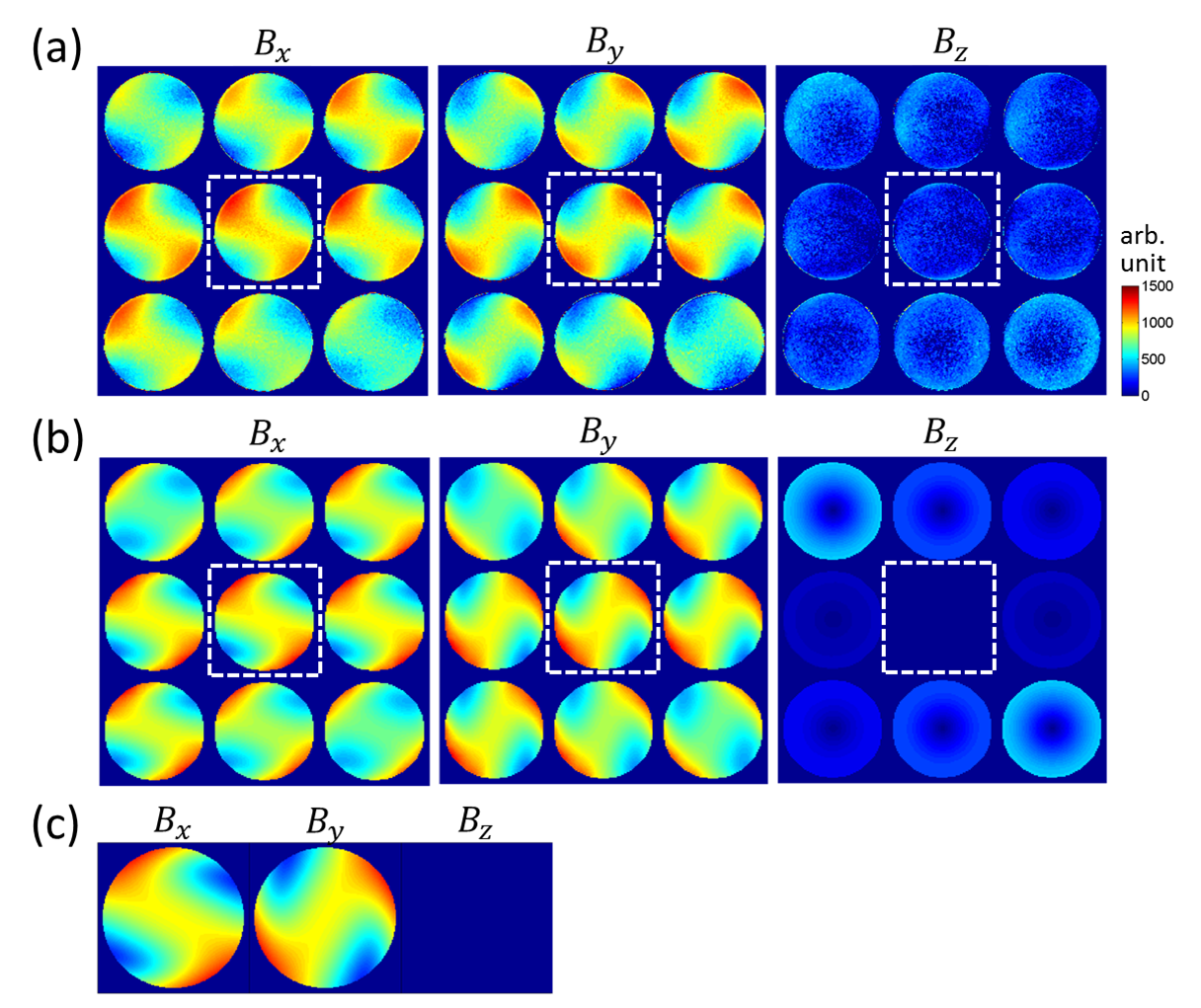
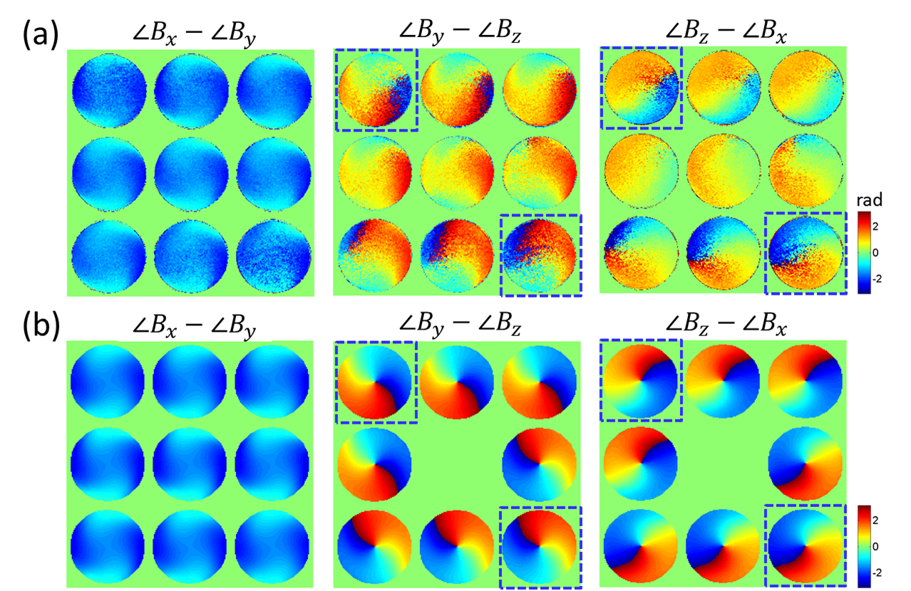
Figure 2 shows the magnitudes of $$$(B_x,B_y,B_z)$$$ reconstructed from experimental data in comparison with simulation. The successive slices are 18 mm apart. The agreement is generally good. The results on the middle slice also agreed well with analytical solutions for an infinitely long cylinder5. Small differences between the experimental and simulated data can be partly attributed to asymmetric positioning of the phantom inside the coil, which was visible in localizer scans (not shown). Our data show the spatial inhomogeneity of the linear components of the transverse B1 field at 3T, and how Bz grows towards the end of the birdcage coil. In the relative phase maps (Fig. 3), the phase of By is about π/2 ahead of Bx, consistent with left circular polarization. Bz phase is sensitive to experimental (positioning) errors due to small Bz magnitudes. Measured relative phases involving Bz resemble simulation better on the end slices where Bz is stronger.Discussion
To our knowledge this is the first experimental demonstration of RF vector field mapping (up to a common phase) in MRI. Our method could inform MR-EPT methodology and SAR modeling. Extension of the method to in-vivo studies obviously requires reduction of the rotation angles as well as streamlining of multi-orientation scan workflow. Given existing literature on multi-orientation human scans for susceptibility6 and $$$B_1^-$$$ mapping7, we do not think this is an insurmountable problem. Future research directions include development of human study-compatible scan protocols and absolute phase determination through additional phase mapping or theoretical constraints.Acknowledgements
This work was supported by IBS-R015-D1.References
(1) Zhang X. et al., IEEE Rev Biomed Engineering 7:87-96 (2014)
(2) Katscher U. et al., NMR in Biomed (2017) DOI: 10.1002/nbm.3729
(3) Wiesinger F. et al., Prospects of absolute B1 calibration, in Unsolved Problems and Unmet Needs in MR, 14th Annual Meeting of ISMRM (2006).
(4) Fautz H.P. et al., B1 mapping of coil arrays for parallel transmission, 16th Annual Meeting of ISMRM (2008), Abstract 1247.
(5) Glover G.H. et al., J Magn Res 64:255-270 (1985)
(6) Liu T. et al., Magn Res Med 61:196-204 (2009)
(7) Lee S-K. and Dixon, W.T., 19th Annual Meeting of ISMRM (2011), Abstract 4429.
Figures