4308
Improved performance of birdcage coils using a split-ring resonator magnetic shield.Carel C. van Leeuwen1, Martijn F. J. Lunenburg2, Stanislav Glybovski3, Peter R. Luijten1, Dennis W. J. Klomp1, Cornelis A. T. van den Berg1, and Alexander J. E. Raaijmakers1,2
1Imaging Division, University Medical Center Utrecht, Utrecht, Netherlands, 2Eindhoven University of Technology, Eindhoven, Netherlands, 3Itmo University, St. Petersburg, Russian Federation
Synopsis
Birdcage body coils make use of an RF shield that degrades B1 homogeneity of the birdcage and increases SAR levels in body parts close to the rungs. A magnetic conductor RF shield would solve this issue. A metamaterial structure of elongated split-ring resonators (SRR) was designed to achieve an artificial magnetic conductor. Simulations and measurements with planar SRR arrays over a dipole are performed. Increased B1+ penetration into phantoms is observed, indicating the shield behaves as a magnetic conductor. Additionally simulations of a birdcage antenna with such shield are performed, which show an improved B1 homogeneity with comparable SAR levels.
Introduction
RF birdcage coils in MRI are typically built with an RF shield to avoid coupling of the birdcage to the gradient coil. Particularly for body coils, the RF shield is preferably placed close to the birdcage rungs to provide a larger bore diameter. However, the efficiency of the birdcage is reduced by the vicinity of the shield. Eddy currents in the shield generate fields of their own that counteract the source currents. The result is that for the same B1 field intensity larger currents are required. These large currents are accompanied by large electric fields that are responsible for the high local SAR levels that are typically seen in the wrists of a subject (figure 1a). This problem could be solved by using a magnetic shield. Unlike a conventional electric shield, the mirror currents in a magnetic shield are oriented in the same direction. (figure 1b) The fields they generate will interact constructively with the source fields. Therefore, the same fields can be achieved with much lower currents in the rungs resulting in lower SAR levels for body parts close to the rungs. The aim of this study is to investigate the feasibility of replacing a traditional electric shield of a birdcage coil with a magnetic shield. Although magnetic conductors do not exist, certain types of metamaterials behave as artificial magnetic conductors (AMCs) at a specific frequency.Methods
To demonstrate the beneficial effect of a magnetic shield for birdcage field patterns, numerical simulations have been performed for a birdcage (radius 79 mm, 8 legs with length 88 mm) with PEC (perfect electric conductor) or PMC (perfect magnetic conductor) shield (see figure 2). An array of elongated split ring resonator (SRR) elements was selected as the most promising candidate to create an AMC for this application. For sake of simplicity, the SRR array was optimized for a dipole antenna over a tissue-like phantom where the dipole would represent one of the legs of a birdcage coil (figure 3b). The B1+ signal at 3 cm depth was evaluated as a function of frequency for no shield, a PMC shield, a PEC shield and the SRR array. In-depth profiles of the B1+ distributions were plotted at the frequency where the SRR was operating in the right mode. Measurements were performed using the setup shown in figure 4a. A dipole antenna and receive loop were connected to a network analyser to measure the transmission into a water phantom at various depths, with: (1) no shield or (2) SRR array behind the antenna. With SRR dimensions determined, a small 7T birdcage coil was chosen as a first aim to test the feasibility of magnetic shielding for birdcage coils. To guarantee that the array of SRRs performs its shielding function correctly - in addition to the beneficial reflective properties - the bottom sides of the SRRs were connected, forming a continuous metal sheet. The optimised array from simulations shown in figure 3 was wrapped around the birdcage and compared to a PEC shield in terms of B1+ and electric field distributions.Results & Discussion
Figure 2a and b show the resulting birdcage H-field patterns. The use of a magnetic shield clearly reduces the currents in the rungs. This translates into lower E-field values, particularly near the endrings of the birdcage. Figure 3b shows that the dipole antenna with a PMC shield clearly outperforms all other setups at all frequencies. The SRR array behaves like an AMC and outperforms the PEC shield over a wide range of frequencies. Figure 4 shows measurement results for a physical implementation of the SRR array with the same setup of a dipole antenna close to a phantom. Figure 4c shows that the measurements reproduce the findings from simulations thereby confirming that the SRR structure operates as a magnetic shield. Figure 5 shows the results for birdcage simulations with PEC shield and SRR-array. The expected reduction in E-fields is not observed. However, figure 5f shows the array greatly improves B1 homogeneity.Conclusion & on-going research
A birdcage coil with magnetic shield provides more homogeneous B1 and lower electric fields. Both simulations and measurements show that a planar SRR structure is able to achieve B1+ penetration depth enhancement, providing confidence that this structure is operating as an AMC. This may prove useful for body imaging at 7T where dipoles are regularly used. Simulations of a birdcage coil with a shielded SRR array has demonstrated equal E-field levels but improved B1+ homogeneity.Acknowledgements
This project received funding from a Horizon2020 FET-Open grant 'M-Cube'References
No reference found.Figures
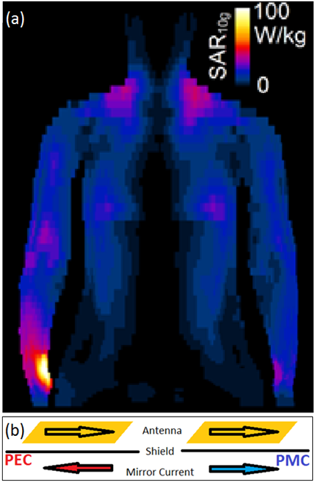
Figure 1: (a)
Simulation of human subject in a 3 Tesla birdcage body coil. Note the SAR
hotspot at the right wrist, close to the endring of the birdcage. (b) Eddy currents in shield create fields equivalent to
mirror currents running on opposite side of the shield. PEC /PMC shields cause
destructive/constructive interference, deminishing/enhancing B1+ per unit
current respectively.
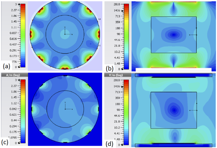
Figure 2: Simulated
H-field distributions in transverse plane (a, c) and E-field distributions in
longitudinal plane (b, d) for a birdcage using PEC (a, b) and PMC (c, d)
shields. Simulations were performed using CST (CST Microwave studios,
Darmstadt, Germany)
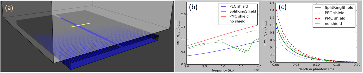
Figure 3: Short antenna simulations using FDTD software (Sim4Life, Zurich MedTech). (a) Simulation setup with
short antenna (1 cm x 10 cm), phantom (σ
= 0.5 s/m, εr = 48) and Shielded SRR array (length: 390 mm, height: 20 mm, width:
4 mm, spacing: 8 mm) Two ports are connected to the far ends of the antenna to
create a homogeneous current distribution. (b) Magnetic field per unit power inside
phantom at 3 cm depth in the center of the phantom. (c) depth profiles in the
center of the phantom at 300 MHz, normalised by input power.
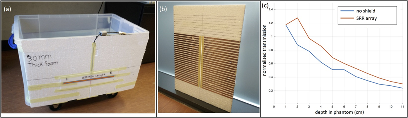
Figure 4: (a)
measurement setup: A dipole antenna and water phantom. (3 g/L Saline) A receive
loop (not shown here) can be positioned in the phantom. A SRR array (length: 330 mm, height: 10mm)
was manufactured (b) (c) depth profiles with and without SRR array. Transmitted
power is computed from the s-parameters as P = S21 / √(1 – S112).
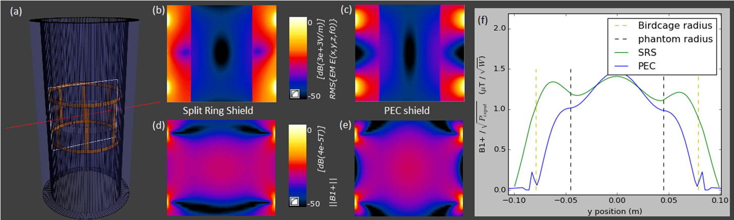
Figure 5: (a)
Simulated birdcage and shielded SRR array. Cylindrical water phantom (σ = 0.5 s/m, εr
= 78) is not shown for clarity. The white rectangle indicates the position of
field distributions b, c, d and e. The red line indicates position of (f). (b)
and (c) show RMS electric field,(d) and (e) show B1+ distributions in the
birdcage for SRS and PEC shield respectively. (f) shows the B1+ distribution in
the center. All plots are normalised to input power at 300 MHz.