4300
Double Facing Miniaturized Patch Antennas with High Permittivity Plugs1Bio Engineering, Pennsylvania State University, University Park, PA, United States, 2Electrical and Computer Engineering, Michigan Tech University, Houghton, MI, United States, 3Mechanical and Nuclear Engineering, Pennsylvania State University, University Park, PA, United States, 4Engineering Science and Mechanics, Pennsylvania State University, University Park, PA, United States, 5Huck Institutes of the Life Sciences, Pennsylvania State University, University Park, PA, United States
Synopsis
Substituting the conventional Radio Frequency coil (RF coil) with a patch antenna has the potential to increase the magnetic field homogeneity in large Fields Of View (FOV). The homogeneity can be improved even more when two of these antennas are facing each other. The size of the patch antennas needed to be reduced to fit inside the scanner bore to use them as RF coils. This was done via inserting high dielectric material plugs. The two facing patch antennas system was also fabricated and tested.
Introduction
Patch antennas have the potential to generate greater magnetic field homogeneity field over a larger Field Of View (FOV) than conventional coils for high field MRI scanners where the electromagnetic wavelengths are small [1]. To be able to use them in preclinical scanners, their size needs to be reduced. A miniaturized patch antenna, fit into a wide bore 14.1 T MRI micro imager, was introduced by Lee et al [2]. Two facing patch antennas were proposed by Gandji et al [1] to create a more homogeneous B1 field. The current work introduces the fabrication and testing of a setup with two facing patch antennas for MRI at 14.1 T. The achieved field homogeneity and a comparison to a single miniaturized patch antenna will be provided.Methods
Two identical miniaturized patch antennas that are facing each other were simulated in CST Microwave Studio (CST of America Incorporated, Framingham, MA, USA). The dimensions, materials, and construction of each antenna are described in [2]. The two antennas were placed 20 mm apart facing each other. In order for those two antennas to create a constructive magnetic field, one of the patch antennas needed to be fed with 180 ° phase shift.
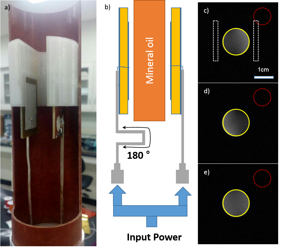
The constructed system (see figure 1a) was tested at 14.1 T. A coupling network was omitted as the high capacitance of the patch antennas prevented a change in matching and tuning when a mineral oil sample was inserted. Furthermore, a higher density silver paint was used to increase the conductivity of the patch antennas.
Two antennas were fed with a phase shift of 180 ° by using cables with the appropriate lengths (figure 1 b). Mineral oil in a 15 mL Falcon tube was inserted and standard gradient echo images with a global flip angle of 40 ° in three orthogonal directions were acquired and analyzed.
Results
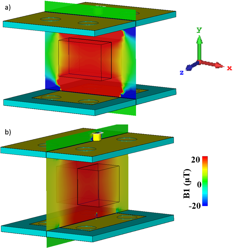
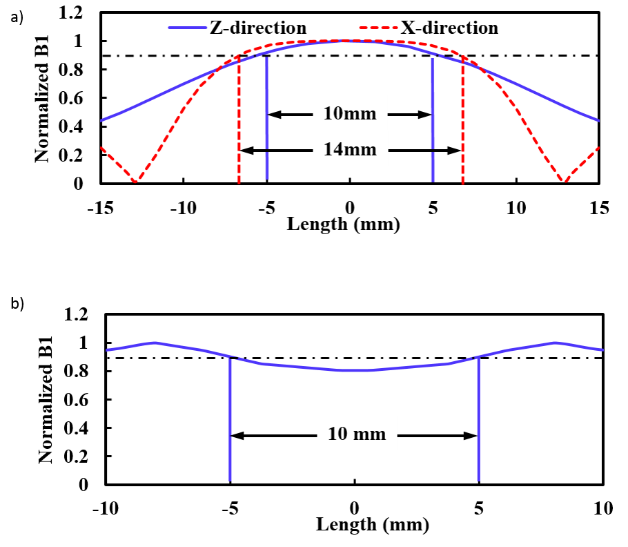
Figure 2 shows the simulated magnetic field from two facing patch antennas. A homogeneous magnetic field can be seen in the xy plane (a) and the yz plane (b) in the middle of the patch. Three orthogonal lines at the center of the setup were plotted in figure 3 a and b. The length of the 10% signal intensity drop from the maximum was 10 mm in the Z and 14 mm in the X direction.
Figure 1 c, d, and e show images from the left side patch, the right-side patch, and when both patches were fed. The signal to noise ratio (SNR) was measured by dividing the average signal indicated by the yellow circle by the standard deviation of the noise in the red circle. The SNR in figure 1 e (SNR = 47) was about 30% higher compared to the SNR of the single patches (1c: SNR = 36; 1d: SNR = 32).
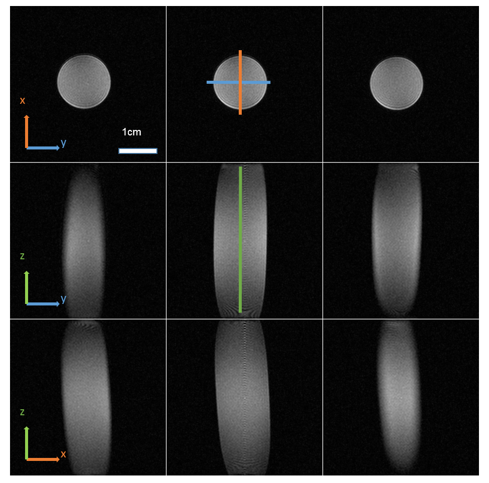
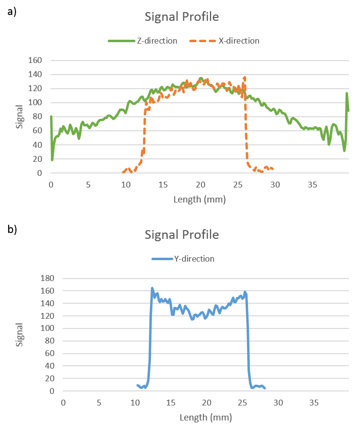
Figure 4 shows two-dimensional gradient echo images taken in all three orthogonal directions with 3 slices in each direction using both patch antennas. Three orthogonal profiles at the center of the phantom are shown in figure 5.
Discussion
The SNR of gradient echo images, especially when imaged with low flip angles, is highly influenced by the pattern of the magnetic field, B1. The simulated and measured facing patch antennas behave in the same manner. The z and x direction plots show the highest value at the center of the double facing antennas system while the y direction plot displays a minimum at the center of the system. The magnetic field of each antenna is highest near the surface of the patch. The drop off of the signal becomes larger as the distance from the patch is increased. The placement of the second patch antenna does not recover the magnetic field homogeneity in this direction.Conclusion
Facing patch antennas at 14.1 T were fabricated and tested. This system created a highly homogeneous field in the center of the two antennas. However, the SNR of the system was much lower than predicted by the simulations. A possible cause may be the lack of a smooth conductor on the electrode of the patch antenna. The weak bond between each particle in the silver paint may have lowered the conductivity, resulting in a lower magnetic field strength than simulated. Future work will concentrate on creating a highly conductive electrode to achieve the B1 field strengths of the simulation results and comparing the setup to conventional volume coils.Acknowledgements
This work is supported by the National Science Foundation under Award DBI-1353664References
[1] N. P. Gandji, A. V. Palle, G. B. Semouchkin, and E. Semouchkina, “Field-simulation based engineering of RF antenna probes with non-uniform substrates for high-field magnetic resonance imaging systems,” Appl. Comput. Electromagn. Soc. J., vol. 31, no. 5, pp. 492–497, 2016.
[2] G. Lee, N. P. Gandji, S. Jung, E. Semouchkina, M. T. Lanagan, and T. Neuberger, “Newly Designed Miniaturized Patch Antenna with High Dielectric Material Plugs,” in proceedings international society magnetic resonance medicine 25, 2017.
Figures