4297
Metamaterial RF Shield with Reduced Specific Absorption Rate and Improved Transmit Efficiency for 9.4 T MRI1the University of Queensland, Brisbane, Australia, 2South China University of Technology, Guangzhou, China
Synopsis
A novel RF shield using metamaterial absorber was designed for 9.4 T MRI. This new design focuses on improving the transmit efficiency of RF coils and reducing the Specific Absorption Rate (SAR) in the subject. A new layered unit cell structure of metamaterial absorber was used for constructing the RF shield. Full-wave simulation results were presented and compared with a conventional copper RF shield; the results suggest that the proposed structure could achieve improved imaging performance.
Introduction
An RF shield is essential to prevent the RF field interfering with other system components during image acquisition1. Conventional RF shields are normally made of slotted copper sheets; the induced surface currents on the shield can reduce the efficiency of RF coils. In recent years, metamaterials have been intensively studied and applied to various areas because of their exotic electromagnetic properties, such as negative permeability and permittivity, which cannot be achieved by natural materials2. One class of metamaterials, the metamaterial perfect absorber (MPA) is capable of achieving near unity absorbance for the incident electromagnetic (EM) waves3. This unique property makes the MPA a perfect candidate for use in an RF shield. In this work, an MPA RF shield is designed for a 9.4 Tesla pre-clinical MRI system. The proposed shield design concentrates not only on a better shielding effect, but also the improvement of Transmit (B1+) Efficiency and the reduction of SAR, which are critical for ultra-high field MRI applications4.
Methods
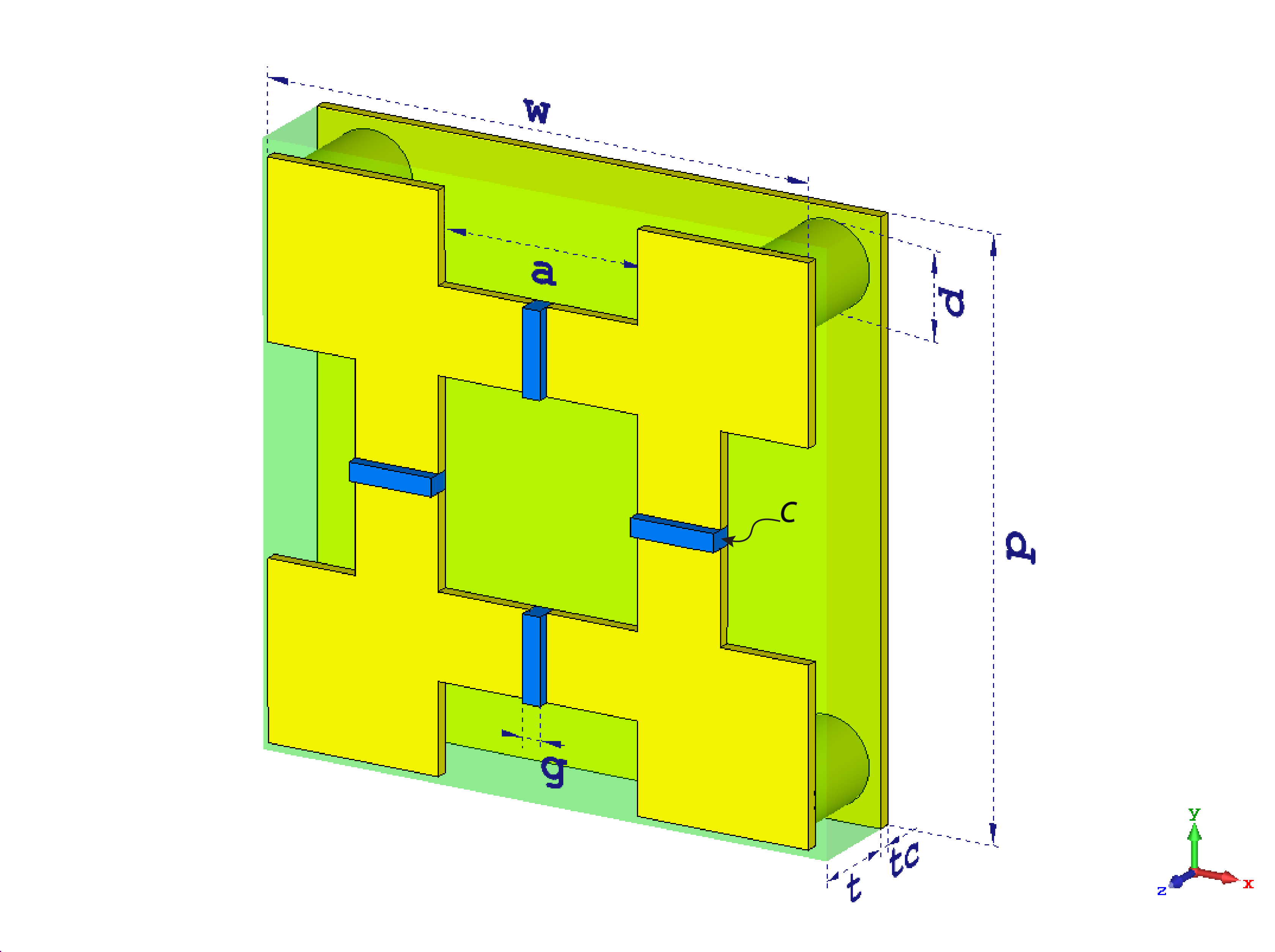
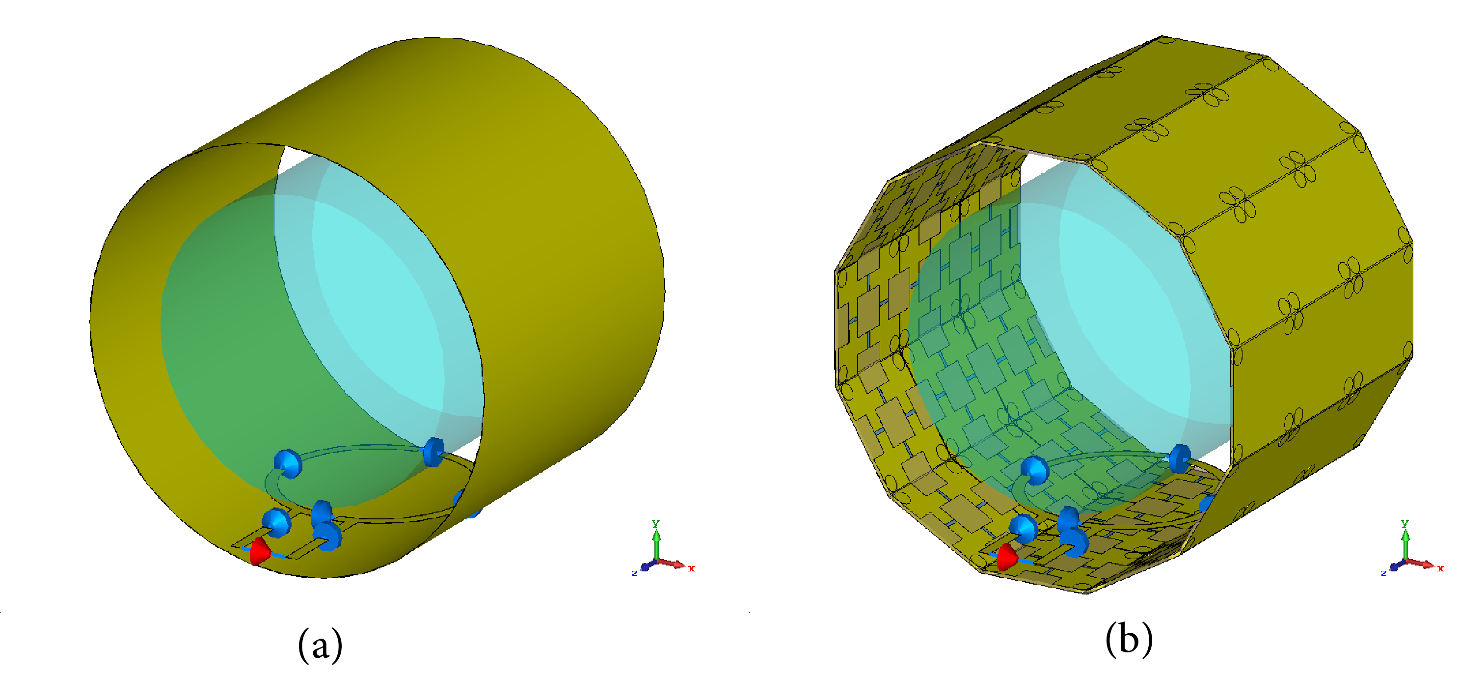
The proposed metamaterial RF shield was designed for a 9.4 T MRI scanner (Bruker Biospin, Ettlingen, Germany) with B-GA20S gradient system ($$$\phi_{inner}$$$ = 200.5 mm). Full-wave simulations were conducted with the finite-difference time domain (FDTD) method using CST Microwave Studio (Darmstadt, Germany). The unit cell consists of a patterned front copper layer, a dielectric substrate layer, a continuous copper back layer and four via copper cylinders in corners (Fig.1). FR-4 board was chosen as the substrate layer, with dielectric constant of 4.3 and loss tangent of 0.03. Perfect absorption can be achieved by simultaneously eliminating EM radiation’s reflection and transmission from MPA5. Since the back of the designed MPA is a continuous copper sheet, only the reflection was considered. The reflection can be minimized by impedance matching. The patterned front copper layer in Fig.1 was developed in order to obtain an effective impedance that perfectly matches the impedance of the propagation medium. As shown in Fig.2(a), 3×12 MPA plates were used to build a dodecagon-cylinder metamaterial shield, with the inner radius of 90 mm. A surface loop coil was placed 10 mm away from a cylindrical phantom. The phantom was designed with radius of 65 mm, height of 120 mm and filled with brain-equivalent material ($$$\epsilon_{r}$$$ = 58.1 and $$$\sigma$$$ = 0.5368 S/m). For comparison purpose, a conventional copper shield (thickness of 17 µm) with the same dimensions was also simulated (Fig.2(b)).Results
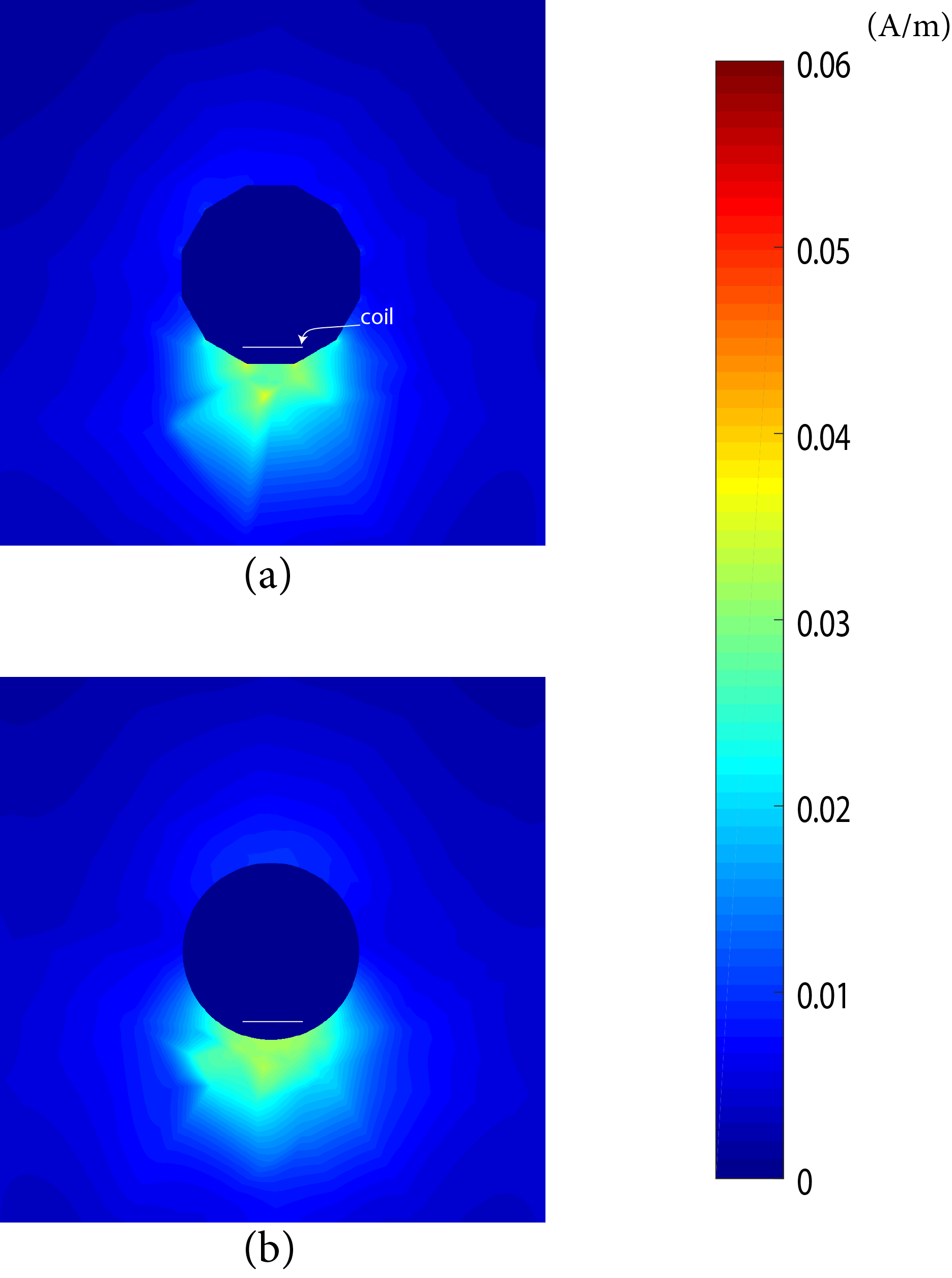
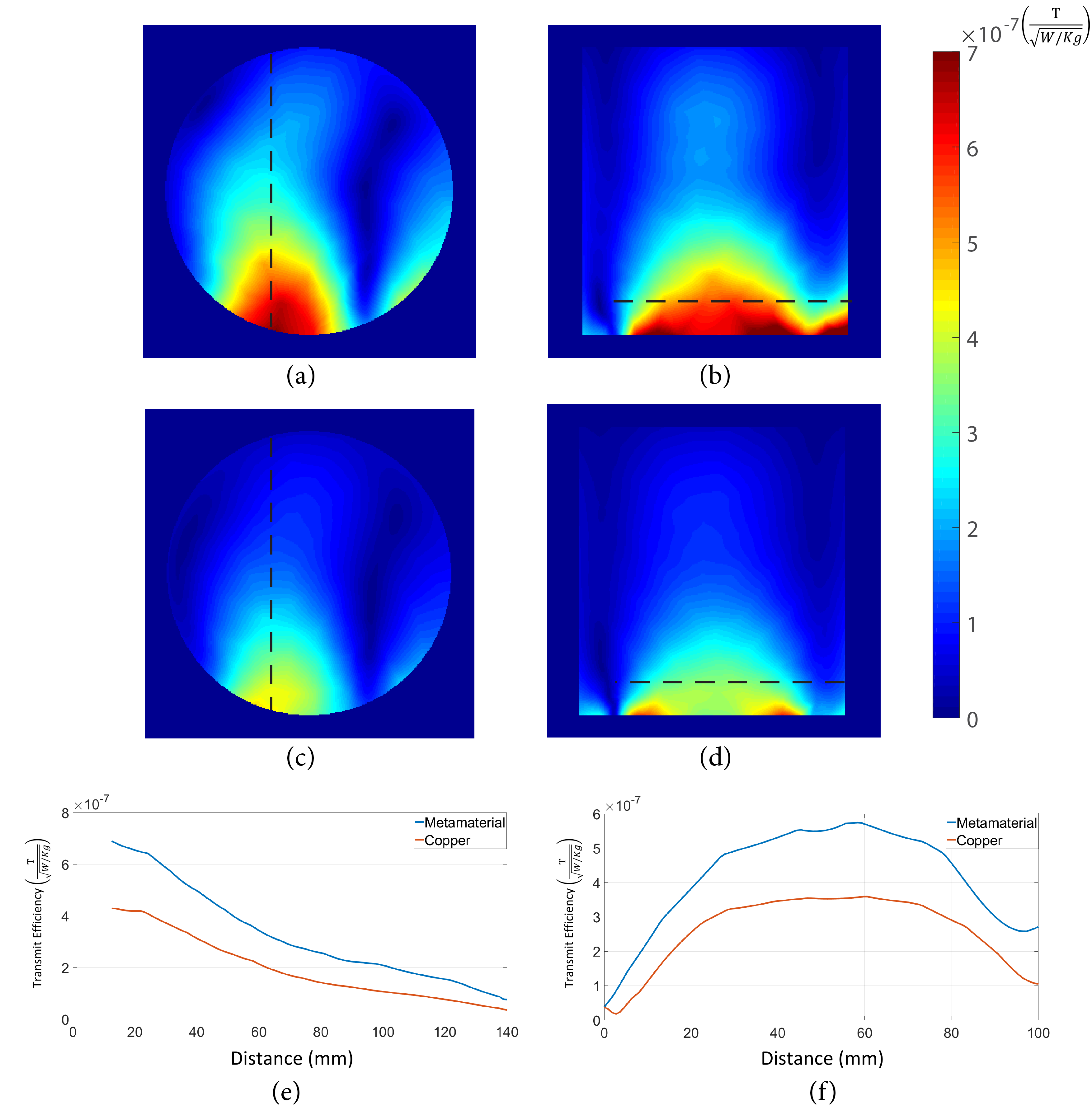
H-field distributions outside MPA shield and copper shield were shown in Fig.3(a) and (b), indicating that both shields provided good shielding effects with little EM leakage (at most 0.035 A/m) outside the shield. The transmit efficiency was normalized by the maximum SAR as: $$$ B^{eff}_{1}=\frac{|B_1 |}{\sqrt{Max(SAR)}}$$$. The transmit efficiency of metamaterial shield and copper shield in the transverse and sagittal planes were shown in Fig.4(a)-(d). It was observed that the MPA shield can improve the transmit efficiency significantly when compared with the copper shield. To quantitatively analyse the transmit efficiency performance, the variations of $$$B^{eff}_{1}$$$ along the black dotted line were shown in Fig.4(e) and (f). The transmit efficiency using the MPA shield was improved by 60.4% when compared with the copper shield. Additionally, the maximum SAR reduced considerably when the MPA shield was used. The simulation results showed that the peak SAR was 3.57 W/Kg when the MPA shield was used; whereas the peak SAR increased to 5.02W/Kg with the copper shield. Results were normalized to the accepted power of 1W in simulation.Discussion
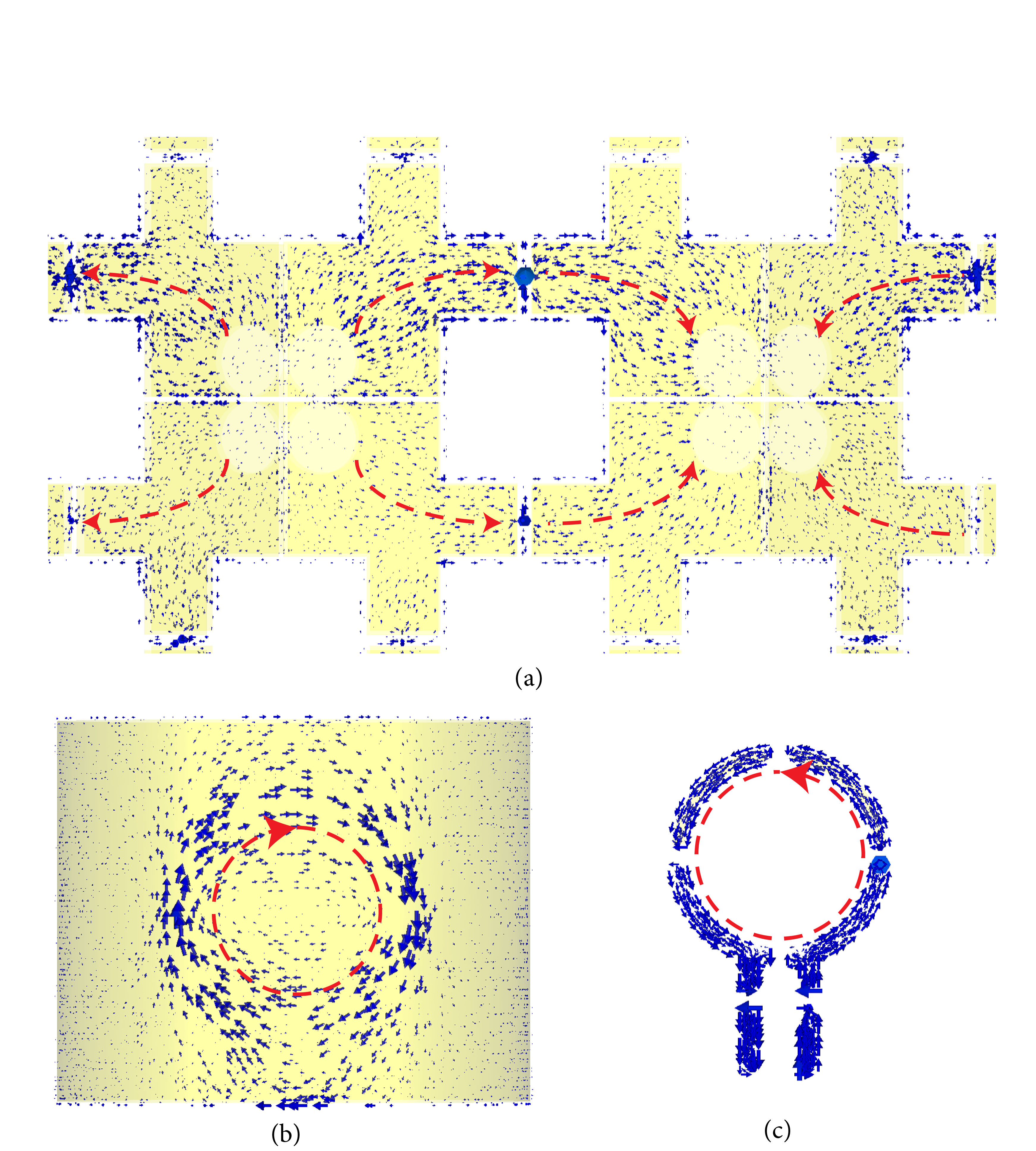
To understand the mechanism of transmit efficiency enhancement with the proposed MPA shield, the induced surface currents on both MPA shield and copper shield were simulated and shown in Fig.5(a) and (b). It is clear that the current induced on the copper shield (Fig.5(b)) has opposite direction to the current flowing on the coil (Fig.5(c)). Therefore, the induced surface current on copper shield undermines the performance of the RF coil by generating opposing EM fields. In comparison, the induced surface currents on each of the unit cell in MPA shield are cancelled out by the current generated on adjacent cells, so that destructive formation of RF field is minimized or prevented (Fig.5(a)).Conclusion
A new design of an RF shield using the MPA was theoretically studied in this work. The proposed MPA RF shield is capable of preventing RF interference between the RF coil and surrounding system components, improving the transmit efficiency and reducing the SAR for 9.4 T MRI system. In the future, the MPA shield will be prototyped and tested on the 9.4T pre-clinical MRI scanner.Acknowledgements
No acknowledgement found.References
1. Roemer PB, Edelstein WA. RF shield for RF coil contained within gradient coils of NMR imaging device. U.S. Patent No. 4,871,969. 3 Oct. 1989.
2. Sihvola A. Metamaterials in electromagnetics. Metamaterials. 2007;1(1):2-11.
3. Landy NI, Sajuyigbe S, Mock J, Smith D, Padilla W. Perfect metamaterial absorber. Physical review letters. 2008;100(20):207402.
4. van Osch MJP, Webb AG. Safety of Ultra-High Field MRI: What are the Specific Risks? Current Radiology Reports. 2014;2(8).
5. Khuyen BX, Tung BS, Yoo YJ, et al. Miniaturization for ultrathin metamaterial perfect absorber in the VHF band. Scientific Reports. 2017;7:45151.
Figures