4293
A Slot Antenna Array for Body Imaging at 7T1Center for Advanced Imaging Innovation and Research (CAI2R), New York University School of Medicine, New York, NY, United States, 2Center for Biomedical Imaging, New York University School of Medicine, New York, NY, United States
Synopsis
Slot antennas have been shown to be promising for body imaging at Ultra High Field (7T). In this work, a 6-channel transmit-receive slot array was constructed, quantitative evaluation of the performance was conducted and practical design features are discussed.
Introduction
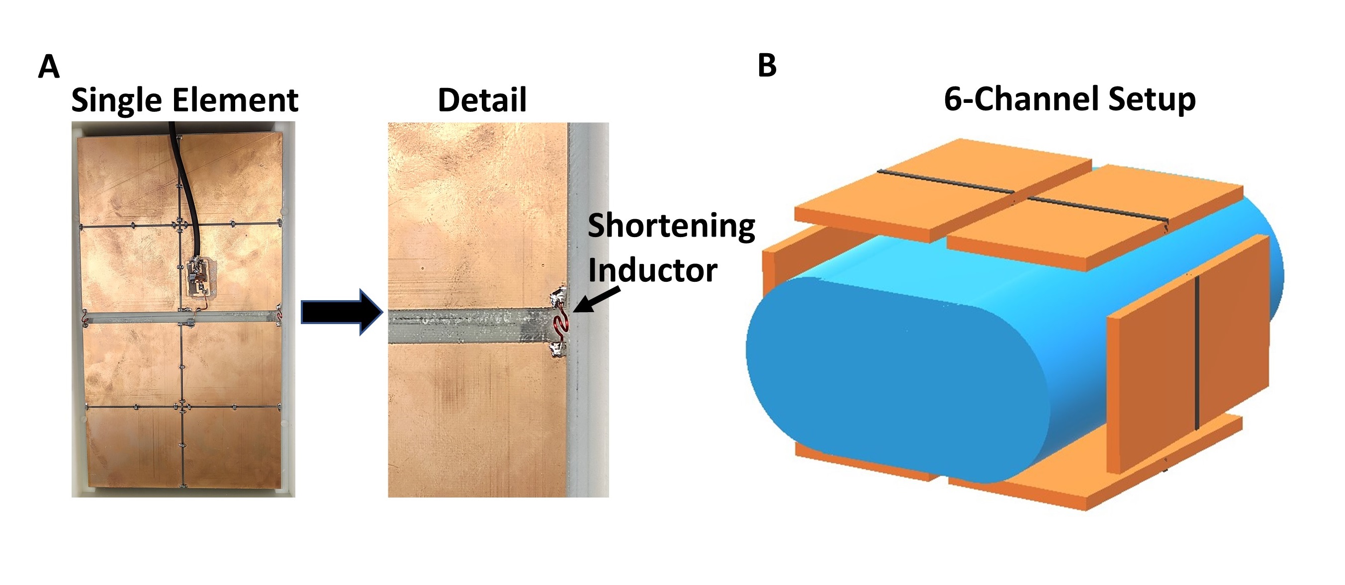
This year, the first 7T MRI system became FDA cleared for the head and extremity regions promising improved visualization of small structures and subtle pathologies [1]. While 7T can potentially enhance diagnosis for the head and extremity regions, body imaging at 7T remains challenging due to: reduction in transmit (B1+) and receive (B1-) field homogeneity and penetration, and increase in peak SAR [2]. To mitigate these effects, the slot antenna design was recently introduced, demonstrating advances in terms of RF field homogeneity and reduction in peak spatial average SAR compared to dipoles [3]. In this work, we built upon the conventional slot antenna design to construct a 6-channel transmit-receive slot antenna array encircling the body. Since slot antennas are conventionally are azimuthally long, we introduced in this work inductors located at the end of the individual slots to increase the electrical length of the current path allowing for a shorter slot facilitating the placement of a larger number of coils around the subject. Preliminary B1+ and SNR maps were acquired on a phantom indicating coverage of a large region with good homogeneity. First images of the hip and prostate regions are presented on a volunteer.
Methods
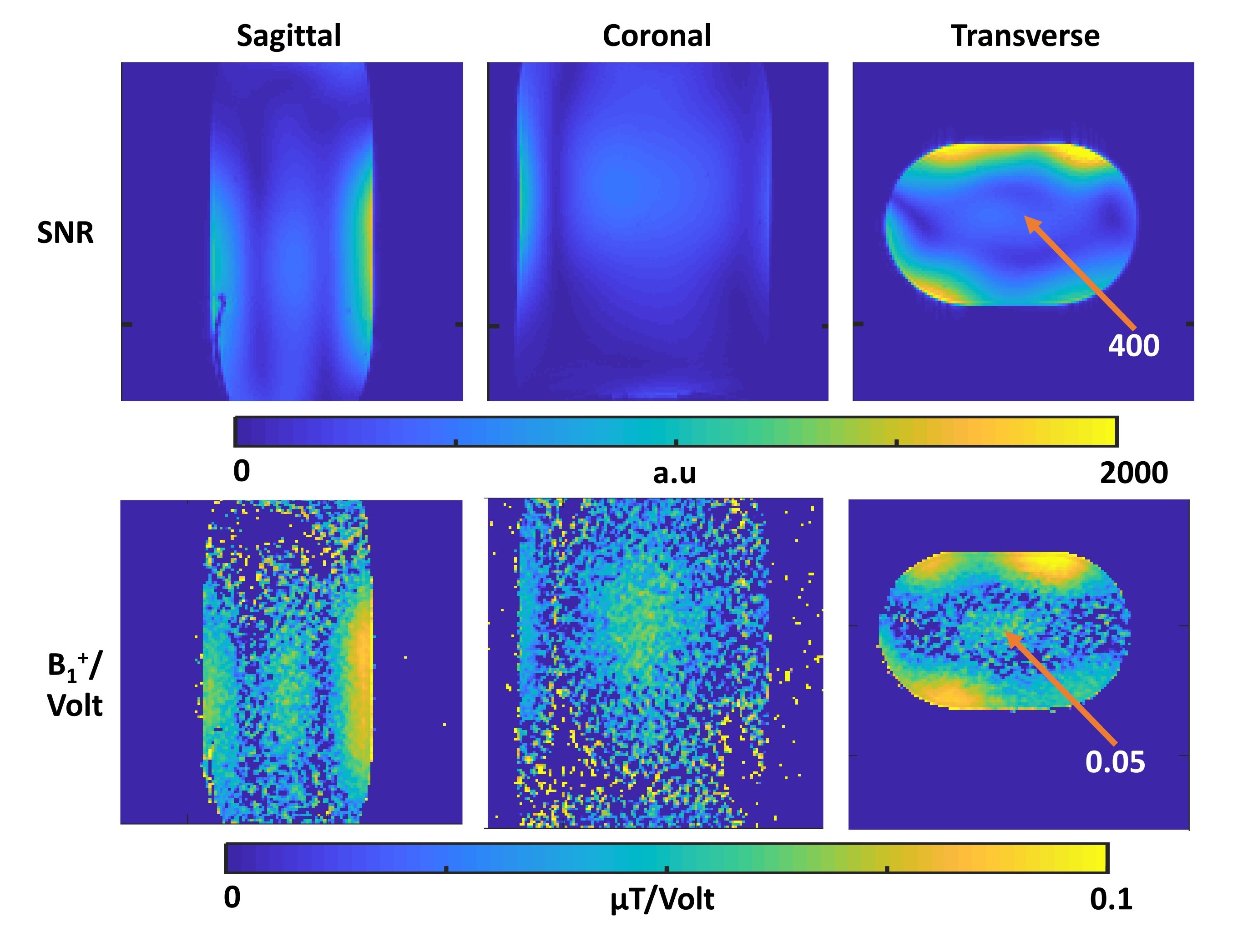
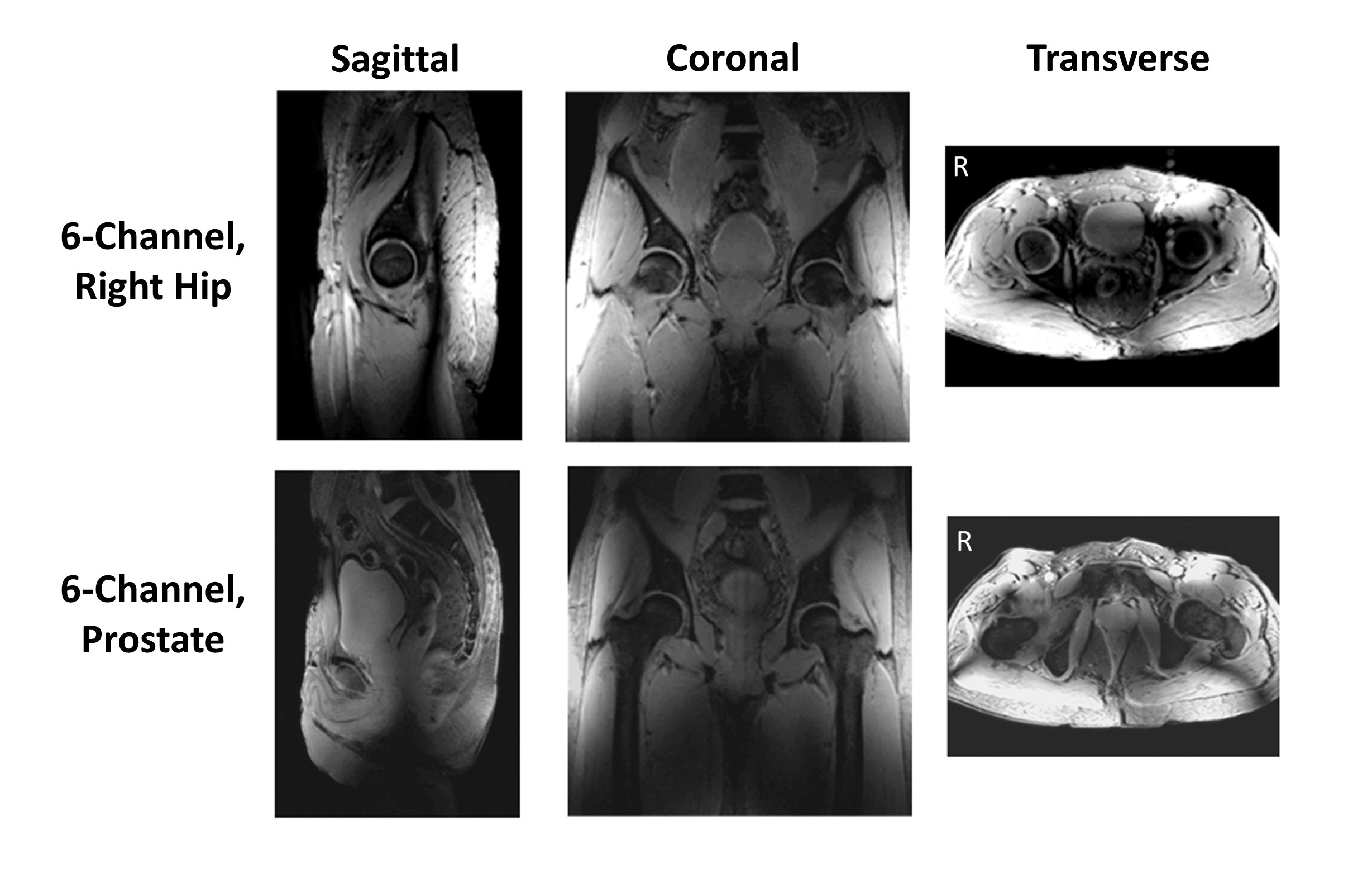
Six identical slot antennas were fabricated from 20 cm (transverse direction) by 33 cm FR4 boards with 31 mil thickness. Narrow gaps in the slots were introduced and 330 pF capacitors were placed across the gaps to block gradient eddy currents. To facilitate practical tuning of these shorter slot antennas, 50 nH solenoid inductors were placed across each end of the slot to increase the effective electrical length of the current path (Fig1A). Placement of the inductors yielded a reduction in the azimuthal length of each slot, allowing placement of more antennas around the body. S11 for each element and S12 between neighboring elements was measured, when the coil was placed around a body phantom with average electrical properties of the body at 300 MHz. Experiments were conducted on a 7T MR system (Siemens Medical Solutions, Erlangen, Germany) in parallel transmit mode. The coil array was placed 3 cm above a phantom (Fig 1B) with an ovular cross section with dimensions of 30 cm (x-direction) by 20 cm (y-direction) by 50 cm (z-direction), with conductivity of 0.62 S/m and relative permittivity of 64.5, respectively. A phase-only shim, producing maximum B1+ at the center of the phantom was established using Siemens' birdcage finder feature. B1+ mapping was conducted using the turbo flash method [4] with the following parameters: FOV=400x400, resolution = 3.1x3.1x5 mm3, saturation pulse reference voltage =73.4 Volts (500 µs rectangular pulse), TR = 5000 ms, and TE = 2.18 ms. Single slice B1+ maps were acquired for axial, sagittal and coronal slices. Furthermore, a spoiled gradient echo and noise images were acquired for axial, sagittal and coronal slices using the following parameters: FOV=400x400, resolution = 3.1x3.1x5 mm3, pulse reference voltage =71.4 Volts, TR = 2000 ms, and TE = 4.07 ms. SNR maps were reconstructed using the Kellman method [5]. The six elements were placed around the pelvis region of a volunteer in the 7T system, with 2 cm between the subject and each coil. Phase-only shim settings were implemented for imaging the right hip and prostate regions in the volunteer.Results
Bench measurements of the S11 and S12 were <-12dB for both, respectively. SNR maps along three principle slices are shown in Fig 2 (top row), with a central SNR of 400 at the center of the phantom for the given sequence parameters. Z-coverage was roughly 35 cm long, coinciding with the z-extend of the slot antennas. B1+ maps yielded a central efficiency of 0.05 µT/Volt, which was equivalent to 30 degrees flip angle for a 73.4 Volt rectangular pulse with 500 µs duration. Feasibility of a 6-channel slot antenna array results are shown in Fig. 3, illustrating the capability to image deep tissues of the hip and prostate regions.Discussion and Conclusion
Preliminary results of a novel slot antenna body array design for 7T is presented in this work. Phantom and in vivo results demonstrate good homogeneity, and reduced SAR (roughly 50% the peak 10g average SAR) compared to a dipole [3]. In this first investigation, the 6-element slot array outperformed a previous 8-element dipole array (on the same phantom, with the same sequence parameters) [6] in terms of SNR, however, transmit efficiency (B1+ per unit Volt) was lower in the slot array. This can possibly be attributed to suboptimal matching and tuning when the slot array was in the scanner bore. Assuming the transmit efficiencies can be improved in further investigations, slot arrays can be a valuable tool towards practical body imaging at 7T.Acknowledgements
Funding from NIH through P41 EB017183.References
[1] FDA clears first 7T magnetic resonance imaging device. www.fda.gov/NewsEvents/Newsroom/PressAnnouncements/ ucm580154.htm. Accessed November 8, 2017. [2] Robitaille P-M, Berliner LJ. Ultra High Field Magnetic Resonance Imaging. Springer Science & Business Media; 2006. [3] Alon et al. Proc. Intl. Soc. Mag. Reson. Med. 24 (2016). P. 3516. [4] Fautz, H-P et al. Proc. Intl. Soc. Mag. Reson. Med. 16 (2008). P. 1247. [5] Kellman P, McVeigh ER. Magn. Reson. Med. 2005;54:1439–1447. [6] Zhang et al. Proc. Intl. Soc. Mag. Reson. Med. 24 (2016). P. 3508.
Figures