4289
Anatomically adaptive coils for MR Imaging – A 6-channel Demonstrator Array study at 1.5 Tesla1Department of Radiology, University Medical Center Utrecht, Utrecht, Netherlands, 2Siemens Healthcare GmbH, Erlangen, Germany
Synopsis
Many of today’s MR coils are still somehow rigid and inflexible in their size. Even highly flexible arrays basically maintain only one specific body-part in a defined range. Anatomically adaptive coils potentially provide the necessary freedom to have a one-size-fits-all design for MRI in clinic. This would lower costs, improve the signal-to-noise ratio (SNR) and increase the patient comfort. To evaluate the potential SNR improvement of adaptive arrays, maintaining an optimal filling factor, a 6-channel Demonstrator array setup, comprised of stretchable loop elements at 1.5T with equal electrical properties as standard elements, was used.
Introduction
Many of today’s MR coils are still somehow rigid and inflexible in their size. Even highly flexible arrays [1, 2] basically maintain only one specific body-part in a defined range. This issue makes it necessary to have several coil arrays to maintain the diversity of patients in clinic. Anatomically adaptive coils potentially provide the necessary freedom to have a one-size-fits-all design for clinically used coils. A decrease in costs per scan, a higher patient comfort and an increased SNR through adaptive coils are potential benefits. Stretchable antennas at 1.5T showed equal electrical properties (e.g. conductivity, resistance) of the used antenna material for the loop elements compared to standard materials [3]. Using stretchable loop elements in anatomically adaptive array, have the potential to maintain a close fit and therefore improved SNR of the MRI coil.Purpose
The purpose of this study was to evaluate the potential SNR improvement by an enhanced filling factor due to anatomically adaptive loop elements within an array.Methods
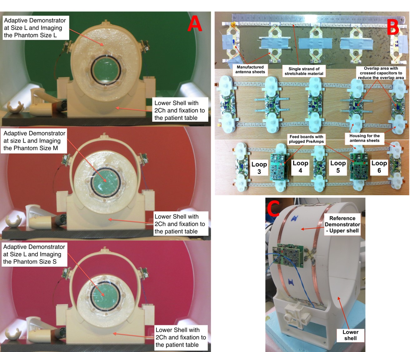
In order to achieve a higher SNR with an improved filling factor through adaptive coils, a prototypical, so-called Demonstrator Array setup was developed to ensure a reliable and valid comparison. To identify the optimal dimensions of the Demonstrator Array a self-programmed Design Tool, and data from anthropometric studies of human knees from U.S. and German clinics in 2015, was used. The experimental setup consists of a lower shell with two rigid loops of 85x60mm of 5mm wide copper tap and two upper shells. The 1st upper shell of 4 rigid loops (122x60mm of 5mm wide copper tape) arranged in one row at a diameter of 180mm is used as a reference array (See Fig. 1C). The 2nd upper shell antenna comprises of 4 stretchable loops (85x60mm) with a stretchable area of xmin= 60.1mm and is designed to fit any extremity dimension between 140 - 180mm (See Fig. 1B). In the rigid overlap area of the stretchable loops, the preamplifier was attached [4].
As stretchable material a 5mm-wide AMOTAPE® conduct elast with PTFE insulated copper strands was used. These strands float in wavy (meander) line along the tape (100% elasticity). The stretchable loops showed an SNR loss of 8.1% in 20mm depth and 8.8% in 50mm depth of the phantom’s surface [3]. All loops were tuned to 63.6MHz using capacitors in the rigid sections of each loop and matched to 50Ω. Adjacent loops were inductively decoupled using critical overlap (-18dB). Residual coupling was suppressed by preamplifier decoupling of around 20dB [5]. The stretchable loops of the adaptive antenna were tuned and matched to the phantom M (Ø140mm) and the loops of the Reference Demonstrator to the phantom L (Ø180mm). The stretchable loops allow a stretching of 52.2% (elongation of 31.4mm) and the whole Adaptive array (including the two rigid loops of the lower shell) allows a stretching of 26.7%.
18 measurements with the two Demonstrator Arrays (adaptive and reference) using three phantoms of 140, 160 and 180 mm in diameter (1.25g NiSO4 x 6H2O per 1000g H2O dist. and 5g NaCl, see Fig. 1A) were conducted on a 1.5T Siemens MAGNETOM Aera (Siemens Healthcare, Erlangen, Germany). We used a spin-echo sequence in transverse orientation (TE=15ms, TR=300ms, FoV=200mm) with a slice thickness of 5mm and an acquisition matrix of 256x256 and a bandwidth of 130 Hz/pixel. The voxel size was 0.8x0.8mm.
Results and Discussion
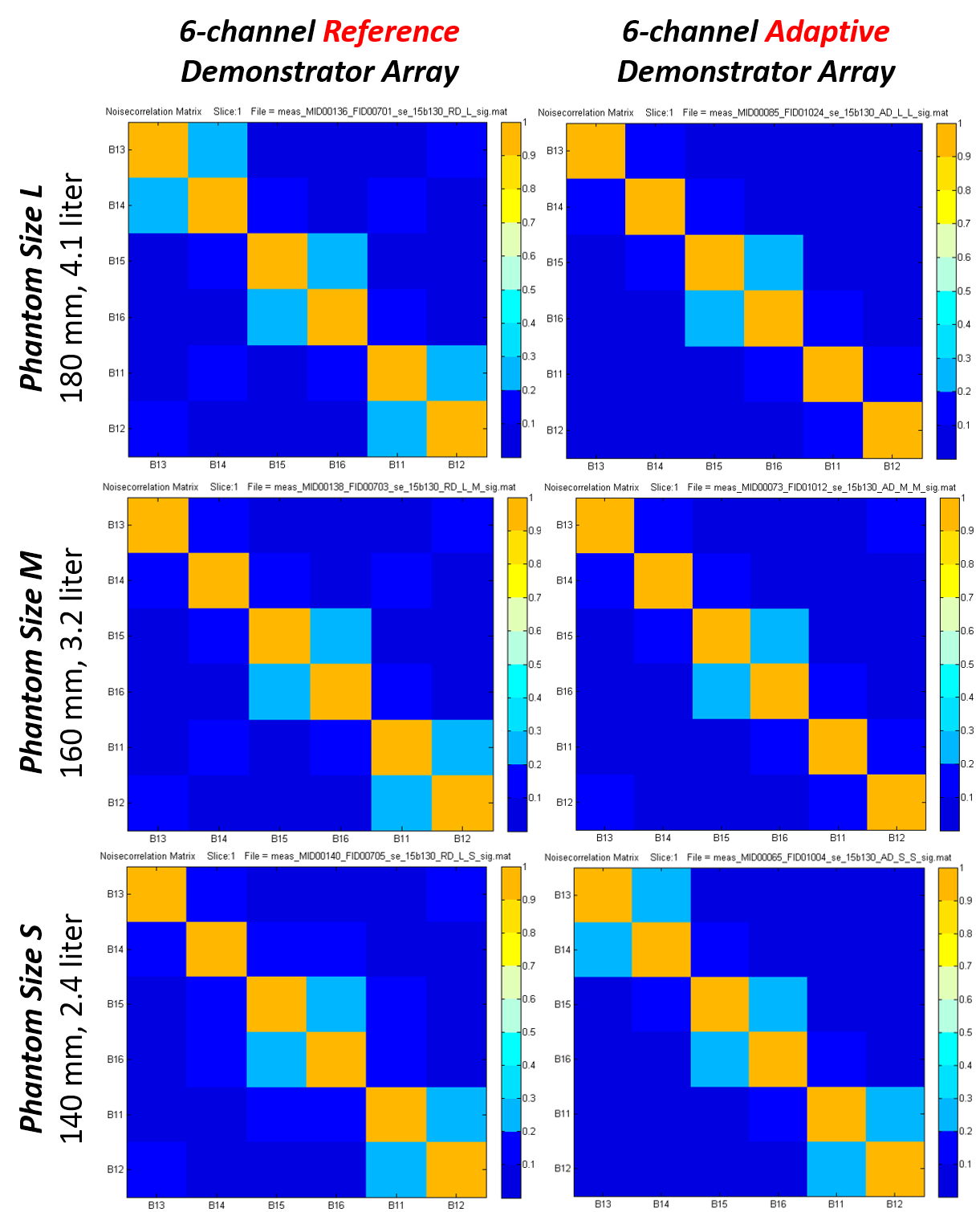
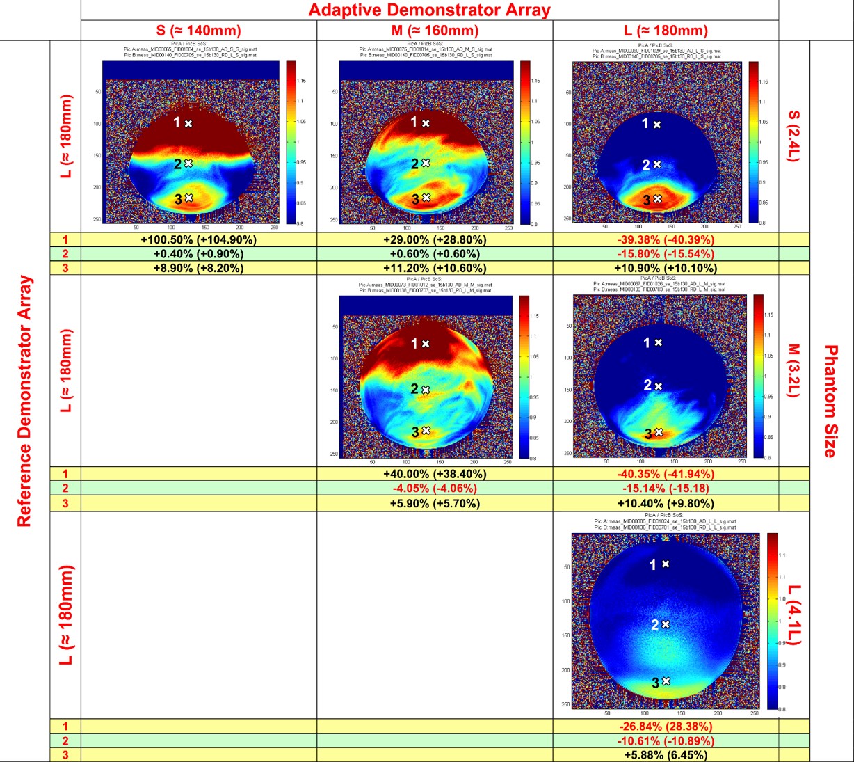
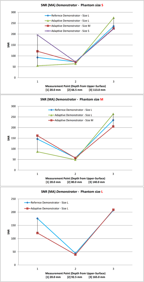
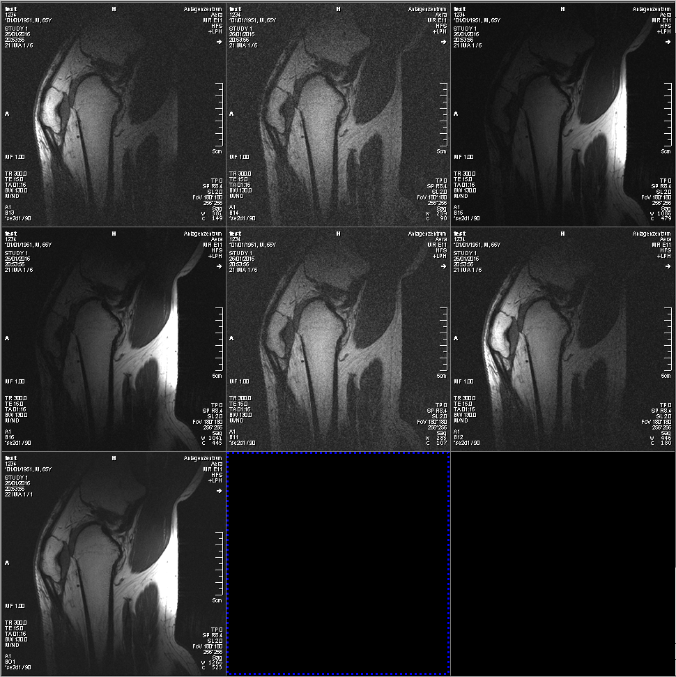
The tuning and matching of the adaptive antenna to the phantom M lowered the expected frequency shift and increased the SNR significantly, when fitting to the other phantoms. The coupling between the elements remained below 0.4 in both setups (See Fig. 2). The Adaptive Demonstrator Array shows an expected SNR loss of 10.8% (MA) in the center of the phantom L compared to Reference Demonstrator. However, the Adaptive Demonstrator showed an SNR gain of 104,9% (MA) in a depth of 20mm from the surface of phantom S compared to the Reference Demonstrator (See Fig 3). This means that an improved filling factor through partly stretchable loops, leads to an enhanced SNR. In the center of phantom M and S, there is a small SNR loss of the adaptive antenna, due to the drawback of the used conductor material (See Fig 4). Combined and single images using the 6Ch Adaptive Demonstrator of a sagittal slice through the center of the knee, can be seen in Fig. 5.Acknowledgements
No acknowledgement found.References
[1] J. A. Nordmeyer-Massner, N. D. Zanche, and K. Pruessmann, „Stretchable coil arrays: Application to knee imaging under varying flexion angles”, Magnetic Resonance in Medicine, vol. 67, p. 872–879, 2012.
[2] S.S. Vasanawala, R. Stormont, S. Lindsay, T. Grafendorfer, J.Y. Cheng, J.M. Pauly, G. Scott, J.X. Guzman, V. Taracila, D. Chirayath, and F. Robb, „Development and clinical implementation of very light weight and highly flexible AIR technology arrays”, Proc. ISMRM, 755, 2017.
[3] B. Gruber, S. Zink, „Anatomically adaptive local coils for MR Imaging – Evaluation of stretchable antennas at 1.5T“, Proc. ISMRM, 543, 2016.
[4] P.B. Roemer, W. Edelstein, C. Hayes, S. Souza, and O. Mueller, „The NMR phased array”, Magnetic Resonance in Medicine, vol. 16, p.192ff, 1990.
[5] B. Keil, J.A. Blau, S. Biber, P. Hoecht, V. Tountcheva, K. Setsompop, C. Triantafyllou, and L.L. Wald, „A 64-channel 3T coil for accelerated brain MRI“, Magnetic Resonance on Medicine, vol. 70, p.248-258, 2013.
Figures