4288
A receive-only, double-tune coil using preamplifier decoupling1Institute of Neuroscience and Medicine - 4, Forschungszentrum Jülich, Juelich, Germany, 2Faculty of Medicine, Department of Neurology, JARA, RWTH Aachen University, Aachen, Germany
Synopsis
In this work we describe two methods for the double-tuned receive only coil design using preamplifier decoupling. Both the LC trap and the lattice balun can be integrated into the receive line to isolate signals resonant at two different frequencies. It was found that the method using LC traps was more effective when the coils were tuned at a higher frequency (normally proton), while the lattice balun method provided higher blocking impedance for the X-nuclei coil.
Purpose
A double-tuned coil can be constructed using two separate concentric loops - one tuned to 1H and the other to X-nuclei1. Although each coil resonates at a different frequency, mutual coupling can cause interfere between the coils, leading to a reduction in coil efficiency2. Preamplifier decoupling is a common method used to reduce the mutual coupling, however it only provides a high-impedance condition at the resonance frequency of the coil3,4. In this work, we describe two circuits which can be utilised to decouple signals at two different frequencies.
Methods
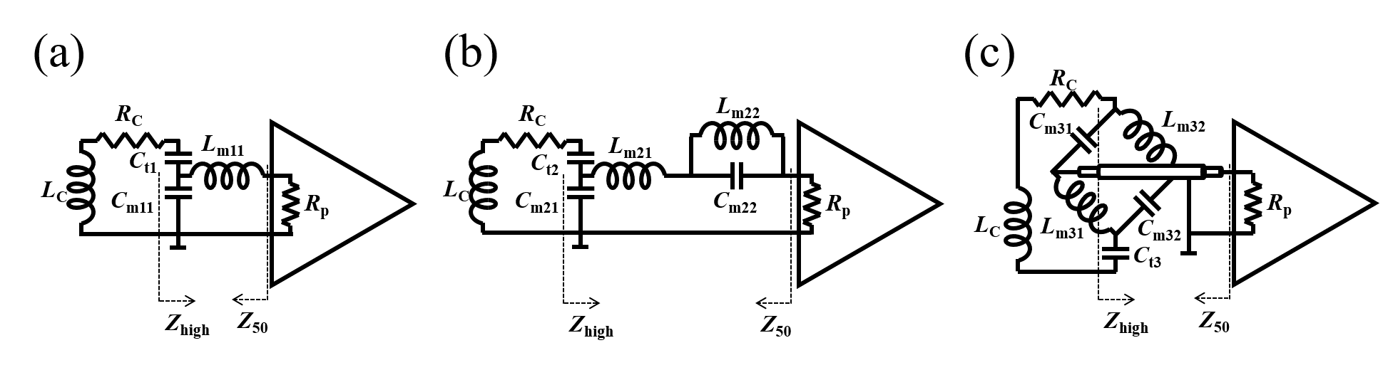
As shown in Fig. 1, three different preamplifier decoupling circuits were designed using a low input impedance (Rp = 0.5Ω) preamplifier. Figure 1a shows a schematic diagram of a simple preamplifier decoupling circuit for a single-tuned coil. When the coil fulfils the three equations below, the coil is matched well to 50Ω and high impedance is present in series, with the loop at the Larmor frequency.
$$X_{L_c}-X_{C_{t1}}-X_{C_{m11}}=0..........(1)$$
$$X_{L_{m11}}-X_{C_{m11}}=0..........(2)$$
$$X_{C_{m11}}=\sqrt{50R_{c}}..........(3)$$
Figure 1b shows a decoupling circuit diagram for double-tuned coil, which includes an LC parallel (trap) circuit. Zhigh is then given as:
$$Z_{high}=\frac{X_{L_{m21}}X_{C_{m21}}-\frac{X_{L_{m22}}X_{C_{m21}}X_{C_{m22}}}{X_{L_{m22}}X_{C_{m22}}}-jR_pX_{C_{m21}}^2}{R_p+j\left(X_{L_{m21}}-X_{C_{m21}}-\frac{X_{L_{m22}}X_{C_{m22}}}{X_{L_{m22}}-X_{C_{m22}}}\right)}..........(4)$$
And Z50, the impedance of the coil as viewed at the preamplifier, can be written as:
$$Z_{50}=\frac{X_{C_{m21}}^2}{R_c}+j\left(X_{L_{m21}}-X_{C_{m21}}-\frac{X_{L_{m22}}X_{C_{m22}}}{X_{L_{m22}}-X_{C_{m22}}}\right)..........(5)$$
Similarly, when the circuit satisfies the equation below, the coil is matched to 50Ω at the resonance frequency and a high impedance is formed for two different frequencies in series with the loop.
$$X_{C_{m21}}=\sqrt{50R_{c}}..........(6)$$
$$L_{m21}=\frac{-C_{m21}C_{m22}(\omega_1^4-\omega_2^4)\pm\sqrt{[C_{m21}C_{m22}(\omega_1^4-\omega_2^4)]^2-4C_{m21}^2C_{m22}\omega_1^2\omega_2^2(C_{m21}+C_{m22})(\omega_2^2-\omega_1^2)^2}}{2C_{m21}^2C_{m22}\omega_1^2\omega_2^2(\omega_2^2-\omega_1^2)}..........(7)$$
$$L_{m22}=\frac{\omega_1^2L_{m21}C_{m21}-1}{\omega_1^2(\omega_1^2L_{m21}C_{m21}C_{m22}-C_{m21}-C_{m22})}..........(8)$$
where ω1 and ω2 are two different resonance frequencies and Lm21 and Lm22 values are the function of resonance frequencies (ω1, ω2) and the capacitance of Cm22.
Figure 1c shows a double-tuned configuration of the preamplifier decoupling using a lattice balun. When Cm31 is not equal to Cm32, this circuit gives a high impedance condition at two different frequencies (ω1, ω2), while when Lm31 = Lm32 and Cm31 = Cm32, it can be used for the single-tuned receive only coil. Capacitors and inductors values are given below as three equations.
$$X_{L_{m31}}-X_{C_{m31}}=0,\text{ } at\text{ } \omega_1..........(9)$$
$$X_{L_{m31}}-X_{C_{m32}}=0,\text{ } at\text{ } \omega_2..........(10)$$
$$X_{C_{m31}}=\sqrt{50R_c},\text{ } at\text{ } \omega_1..........(11)$$
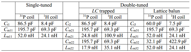
The Z50 and Zhigh of each circuit shown in figure 1 were calculated to apply for the 31P (49.87MHz)/1H (123.20MHz) double tuned coil at 3T. Rp, Rc, and Lc values were considered as 0.5Ω, 2.8Ω, and 36.3nH, respectively. Values of all the other components were calculated using the equations above.
Results
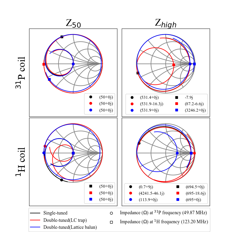
Table 1 shows the components values calculated for the preamplifier decoupling. Both impedances Z50 and Zhigh were plotted on the Smith Chart over a frequency range of between 42.5MHz and 130.5MHz, as shown in figure 2. The left column data in figure 2 shows the loops are matched well to 50Ω at each frequency. The high impedance values of the three different configurations were almost the same at their resonance frequencies (531Ω for 31P loop, 695Ω for 1H loop). High impedances at 1H frequency of the 31P coils, using the LC trap and the lattice balun were 87Ω and 3.2kΩ, respectively. High impedance at the 31P frequency of the 1H coils using the LC trap was 4.2kΩ and using the lattice balun was 114Ω.Discussion
It was shown that two different matching networks can be used for blocking the coupled current at two different frequencies, while the coil is matched to 50 Ω at one resonance frequency. The capacitor and inductor values required for preamplifier decoupling are also demonstrated. When the coils are tuned to the 31P frequency, the calculated high impedance at 31P frequency were almost same - 531Ω. However, high impedance at 1H frequency of the 31P coil using lattice balun is much higher than that of LC trap. In contrast, the high impedance at 31P frequency of the 1H coil using the LC trap is considerably higher than that of the lattice balun, while high impedances at 1H frequency were nearly same - 695Ω. In reality, the input impedance of the preamplifier is not exactly Rp at both frequencies, since phase of the input impedance is shifted at least one frequency. However, suggested matching networks can still be used for the preamplifier decoupling by adjusting the Lm22 and Lm32 values.Conclusions
Both suggested methods for preamplifier decoupling can be used to decouple signals at two different frequencies. Simulation results show that the performance of the lattice balun method is superior to that of the LC trap method when the loop is tuned at a lower frequency, in terms of high impedance, especially at higher frequency. On the other hand, the performance of the LC trap method is outstanding when the loop is tuned at a higher frequency. We now intend to build a double-tuned receive only coil with separate loops for each frequency, using the suggested preamplifier decoupling method.Acknowledgements
No acknowledgement found.References
1. Alecci, M., Romanzetti, S., Kaffanke, J., Celik, A., Wegener, H. P., & Shah, N. J. (2006). Practical design of a 4 Tesla double-tuned RF surface coil for interleaved 1 H and 23 Na MRI of rat brain. J. Magn. Reson., 181(2), 203-211.
2. Fitzsimmons, J. R., Beck, B. L., & Ralph Brooker, H. (1993). Double resonant quadrature birdcage. Magn. Reson. Med., 30(1), 107-114.
3. Roemer, P. B., Edelstein, W. A., Hayes, C. E., Souza, S. P., & Mueller, O. M. (1990). The NMR phased array. Magn. Reson. Med., 16(2), 192-225.
4. Reykowski, A., Wright, S. M., & Porter, J. R. (1995). Design of matching networks for low noise preamplifiers. Magnetic resonance in medicine, 33(6), 848-852.
Figures