4287
Wavelength independent λ/40 Composite Right/Left-Handed Transmission Line Coil1INM-4, Forschungszentrum Jülich, Jülich, Germany, 2Department of Neurology, JARA, RWTH Aachen University, Aachen, Germany, 3INM-11, Forschungszentrum Jülich, Jülich, Germany
Synopsis
A Dual Series (DS) Composite Right/Left Handed (CRLH) Microstrip Transmission Line (MTL) coil for MRI was designed and verified in a commercial 3T Scanner. According to metamaterial theory, we demonstrate the existence of the right-handed leaky mode to be in the UHF region. For design proposes we propose an equivalent circuit parameter extraction method and demonstrate that the phase velocity of the DS-CRLH MTL coil’s guided mode is located in a fast wave region.
Introduction
A microstrip transmission line (MTL) structure is frequently used as an element for parallel transmission (PTx) at ultra-high field MRI1,2 . The MTL coil length is determined by the wavelength and element termination. Common length are 25 cm or less at 7T and above2. This type of coil can be tuned using two capacitors attached at both ends. However, if a suitably homogeneous current distribution is desired the MTL element becomes rather short and does not achieve full brain coverage. As alternative, composite right/left handed (CRLH) structures have been introduced3,4. In this study, we propose a symmetric and wavelength independent coil, derive the design equations and demonstrate its performance in a MRI experiment.Methods
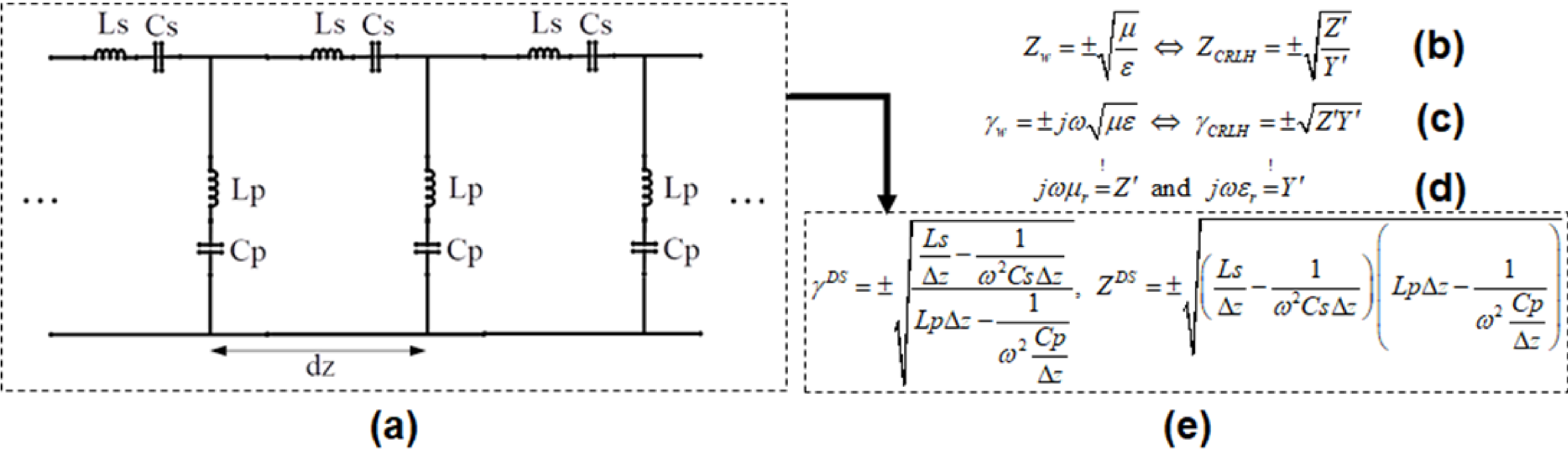
The 1-D periodic structure shown in Fig. 1-(a) can be described in the form of a complex immittance transfer function with the relations given in Fig. 1-(b) to (d). As can be seen from Fig. 1-(e) the TL propagation constant has two solutions allowing propagation of two modes which makes the circuit a Dual-series (DS) CRL3-5. The dispersion relation gives information about the group/phase velocities as function of operating frequency. In order to analyze this, it is necessary to extract the CRLH parameters (Ls, Cs, Lp, and Cp) for the equivalent circuit shown in Fig. 1-(a). The serial inductance (Ls) and capacitance (Cs) can be obtained by extracting the Y21 value from the full EM simulation of the unit cell structure, e.g. using CST MWS (CST AG, Darmstadt Germany), and calculating the series inductance/capacitance value by using the reactance definition: Ls = Im(1 / Y21) / 2πf and Cs =1/(2πf * Im(1 / Y21) ). The parallel capacitance (Cp) and inductance (Lp) can be freely chosen to suit the desired TL inductance6. Finally it has to be verified that the chosen dual series reactance, Im(ZDS), is a monotonically increasing function that satisfies the Foster theorem7.
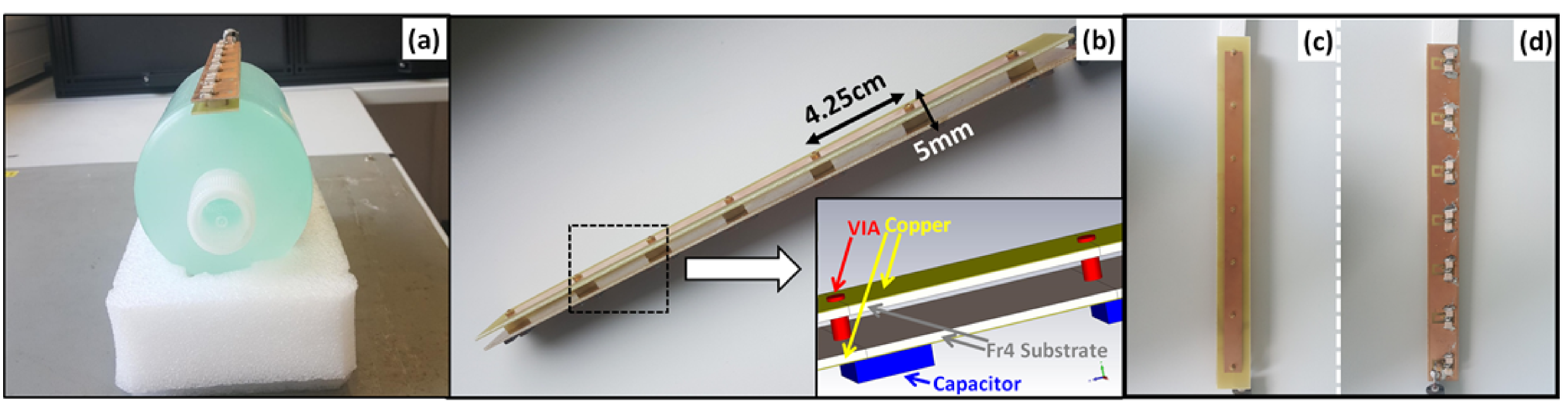
On the basis of the theory presented above, a λ/40 length CRLH unit-cell was designed and used to construct a TL coil element shown in Fig. 2-(b). Dimensions are 4.25cm for the unit cell and the entire coil spans 6 unit cells with 5mm gap between shield and coil. 10pF and 3.9pF capacitors were used in parallel to tune the coil to 123.2MHz. A 5.6pF capacitor was used to match the element to 50Ω. The coil response was characterised on the bench by measuring the return loss (S11) using a vector network analyzer. MR experiments were carried out on a 3T clinical MRI scanner using a uniform cylinder phantom (outer diameter = 11cm, length = 25cm). A standard 2D FLASH sequence (TR/TE = 65ms/2.81ms, matrix size = 256x256, FOV = 250x250mm2 and slice thickness = 3mm) was used to acquire central transverse, coronal and sagittal images.
Results
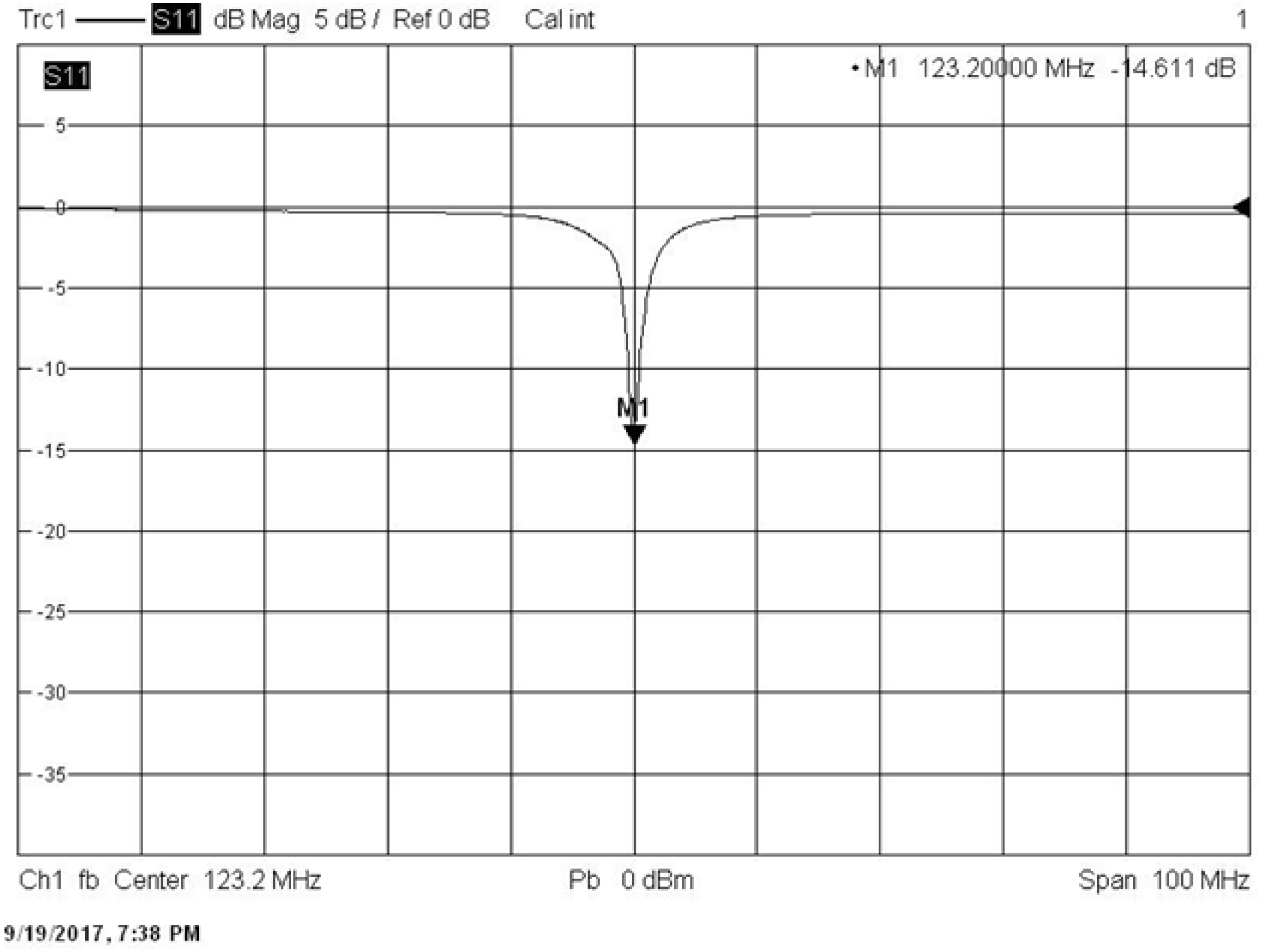
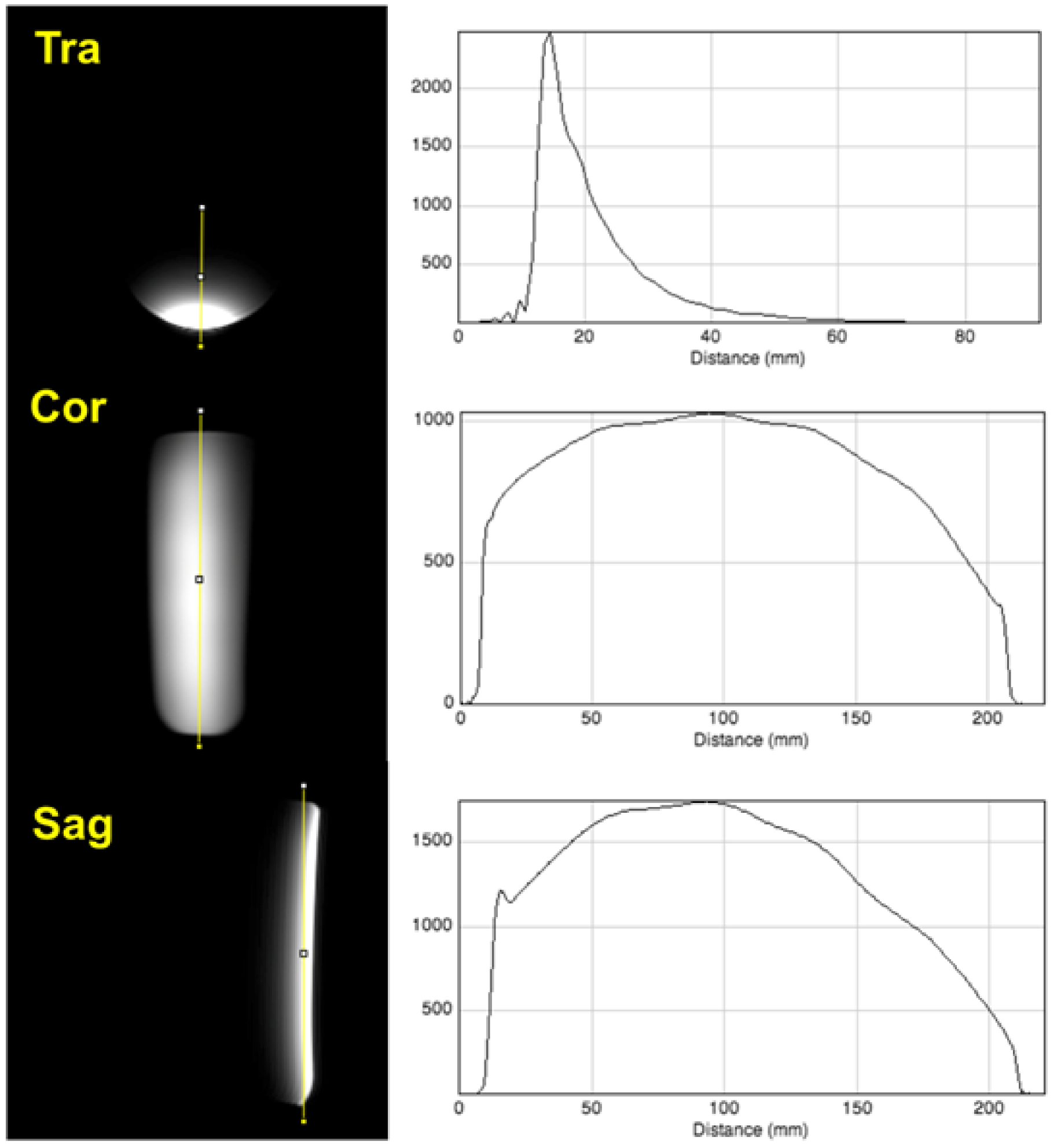
The CRLH parameters derived from the transfer function approach have two possible solutions. The solution with a monotonically increasing reactance, Fig. 3-(a), has been chosen. They allow one to determine the electronic bandgap characterized by a propagation constant of zero (Fig. 3-(b)). In the chosen implementation it is below 80MHz. Thus, according to the Fig. 3-(c), the proposed CRLH TL operates in the fast wave region which is between approx. 80MHz to 500MHz. As ωs<ωsp, compare Fig. 3-(d), the propagating leaky wave is right handed3. Fig. 4 shows the return loss (<-14dB) of the coil measured on the bench with the phantom. Fig. 5 displays the transverse, coronal and sagittal images with their associated profiles. They indicate a general MTL-like B1+ distribution without dark regions possibly caused by concatenating several CRLH TL unit cells.Discussion and Conclusion
We have presented the theory of the wavelength independent CLRH TL element whose physical length can be varied in multiples of unit cell dimensions. First images showed B1+ profiles comparable to these of MTLs. The presented general approach can be easily adopted for higher field strength and will be investigated in array configurations for coupling performance in a next step.Acknowledgements
No acknowledgement found.References
1. Adriany, G., et al., Transmit and receive transmission line arrays for 7 Tesla parallel imaging. Magnetic resonance in medicine, 2005. 53(2): p. 434-445.
2. Shajan, G., et al., Design and evaluation of an RF front‐end for 9.4 T human MRI. Magnetic resonance in medicine, 2011. 66(2): p. 594-602.
3. Damm, C., Artificial Transmission Line Structures for Tunable Microwave Components and Microwave Sensors. 2010: Shaker.
4. Lai, A., T. Itoh, and C. Caloz, Composite right/left-handed transmission line metamaterials. IEEE microwave magazine, 2004. 5(3): p. 34-50.
5. Caloz, C., Dual composite right/left-handed (D-CRLH) transmission line metamaterial. IEEE microwave and wireless components letters, 2006. 16(11): p. 585-587.
6. Grover, F.W., Inductance calculations: working formulas and tables. 1946: New York : D. Van Nostrand Co.
7. Foster, R.M., A reactance theorem. Bell Labs Technical Journal, 1924. 3(2): p. 259-267.
Figures