4286
Comparison of single-loop endoluminal receiver coils based on serial or parallel active decoupling circuits using controllable MEMS switches1Univ. Lyon, INSA-Lyon, Université Claude Bernard Lyon 1, UJM-Saint Etienne, CNRS, Inserm, CREATIS UMR 5220, U1206, F-69000, LYON, France, 2General Electric Healthcare, Buc, France, 3General Electric Healthcare, Aurora, OH, United States
Synopsis
Two prototypes of single-loop endoluminal receiver coils integrating serial and parallel active decoupling circuits using controllable MEMS switches were built and compared to a reference coil with PIN-diode circuit. Parallel MEMS coil had a significantly higher quality factor compared to the serial MEMS coil and the reference coil. The switching delays of both MEMS coils were about few microseconds (< 8µs). The characterization on 3.0T MRI system showed comparable signal intensity distribution for the different coil configurations.
Introduction
The use of
receiver endoluminal coils is an attractive method to achieve locally high
spatial resolution in deep regions in the body such as colon wall1,2. During the radiofrequency
(RF) transmit phase, the receiver coil must be decoupled from the RF
transmitter coil. This is to avoid inhomogeneity of the RF magnetic field in
proximity of the receiver coil and the extra noise in the image due to the
mutual inductance between coils3.
For this purpose, several detuning methods were proposed in literature mainly
based on PIN-diodes4.
However, PIN-diodes have several constraints (high current bias, high
RF current circulation, need of chokes)5.
To overcome these limitations, GE Healthcare has recently introduced Micro
Electro-Mechanical System (MEMS) switches6.
In the following study, we compare the use of controllable MEMS in different
configurations to PIN-diode for active decoupling and overall RF coil
performances in the case of miniature loop coils for further endoscopic
purpose.Methods
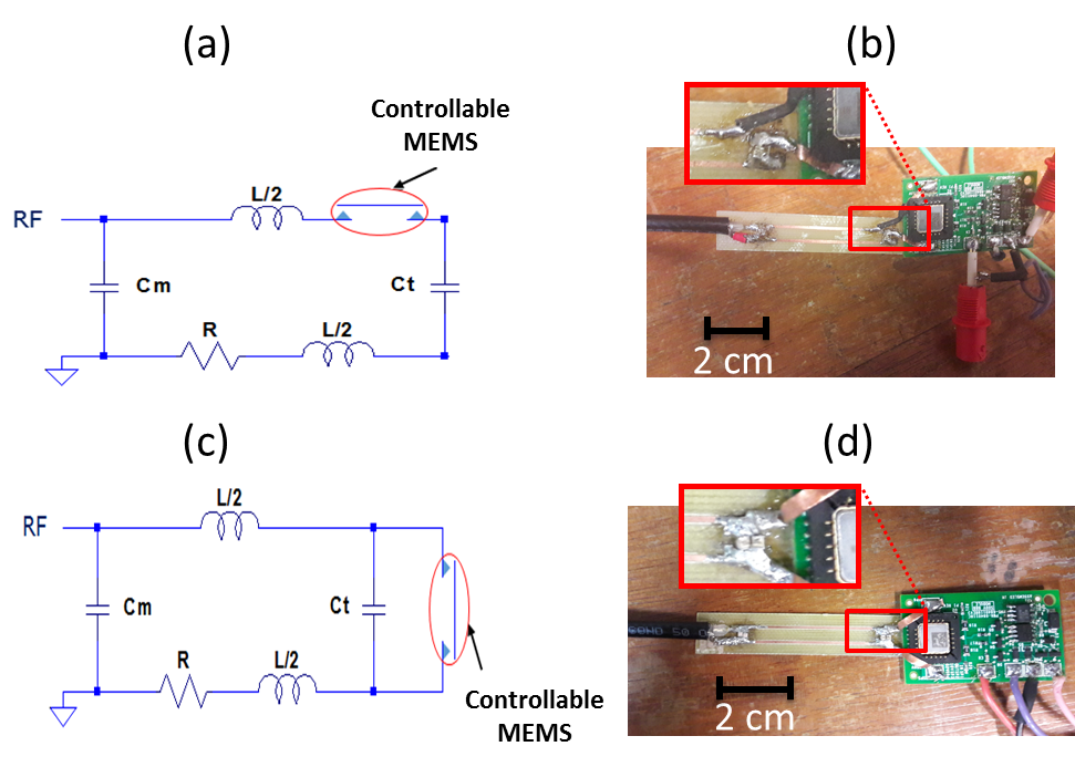
Two endoluminal receiver coils were built to operate at 127.73MHz, based on a rectangular single-loop associated to a controllable MEMS switch. The latter can be closed or opened by applying through its driver circuit a control signal of -5V or 7V voltages, yielding respectively 82V or 0V at the MEMS input. The MEMS switch was integrated in series (figure 1a,b) and in parallel (figure 1c,d) to the RF-loop. These prototypes were compared to a reference coil based on a PIN-diode placed distally in parallel to the loop. The three coils were characterized using a cylindrical phantom (solution of 1.25g NiSO4x6H2O+5g NaCl per liter of distilled water) mimicking tissue losses on experimental electronic benches and on a clinical GEHC 3.0T MRI system. The RF coils were connected to a Vector Network Analyzer to measure the frequency response of the reflection coefficient in both coupling and decoupling modes. Then, resonance frequency, matching coefficient, quality factor Q and decoupling coefficient of the RF coils were derived. The switching delays for both coupling and decoupling modes were then estimated using a digital oscilloscope by measuring transmitted RF generated signal delays following the coupling/decoupling DC commands. Finally, receiver coils were characterized in imaging conditions using the body coil for RF transmission and a gradient echo sequence to estimate the Signal-to-Noise Ratio (SNR).Results
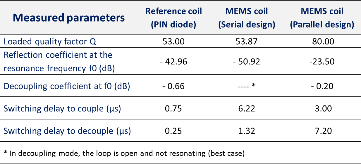
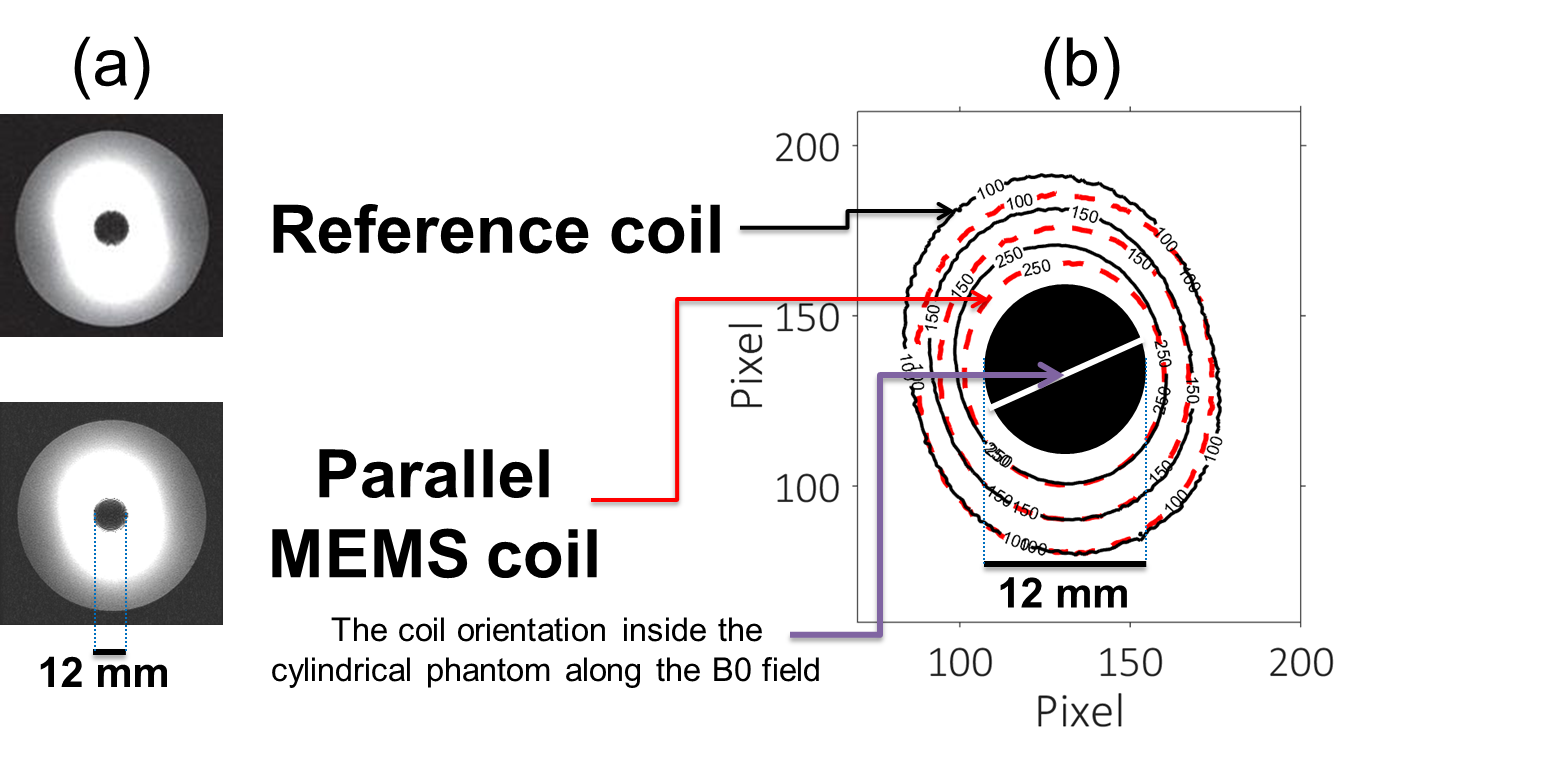
Table-1 summarizes the electronic parameters characterizing the different RF coil prototypes. In serial design the loop was able to be opened or closed. In parallel design, the quality factor was the highest and the decoupling coefficient (isolation) was less than -0.2dB. The switching delays were lower than 8µs for both MEMS circuits and lower than 1µs for PIN-diode circuit. Figure 2 shows comparable intensity distribution and SNR-isocontours for all coils. The high SNR close to the coil decreases rapidly with the distance.Discussion
The parallel MEMS coil has a significantly higher Q-value (~80) compared to the other prototypes (around 53). In fact, in receive mode, the MEMS is open (similar to a capacitor of about 1.5pF) for the parallel design and closed (similar to an additional resistance of about 0.5Ω) for serial design. Thus, in the latter, the parasitic resistance of the MEMS degrades the achievable Q-value. In coupling and decoupling modes, the reflection coefficient measurements show an efficient impedance matching and an efficient decoupling coefficient (~0dB) respectively for all coils. The difference between switching delays of serial (6.2µs) and parallel (7.2µs) MEMS designs is due to the location of the switch into the coil. Knowing that the switching delays of the MEMS alone is below 4µs, the observed increase in both MEMS coils is mainly due to the driver circuit effect. In the reference coil, the delay is shorter (1µs) mainly due to the absence of a driver circuit. Nevertheless, MEMS switching delays are compliant with MR purposes. With regard to imaging, SNR-isocontours of MEMS-based circuits do not exactly overlap that of PIN-diode-based circuit. The underlying SNR degradation is induced by electromagnetic coupling with external cables used to power the driver circuit for both serial and parallel MEMS designs. We are currently investigating more efficient shielding strategies to remove additional noise through these cables.Conclusion
We built and characterized receiver endoluminal coils using MEMS switches for serial and parallel active decoupling circuits. We obtained relevant performances for the RF coil based on parallel MEMS compared to the reference RF coil, particularly in terms of the quality factor (~25% gain). For future work, we will study the feasibility of using the serial MEMS switches for reconfigurable endoluminal coils in order to keep relevant signal sensitivity pattern regardless of coil orientation with respect to B0.Acknowledgements
Authors would like to thank the LABEX PRIMES of University of Lyon, which has supported this work within the program "Investissements d'Avenir" (ANR-11-IDEX-0007) operated by the French National Research Agency (ANR).References
1. Hurst G C, Hua J, Duerk J L, & Cohen A M. Intravascular (catheter) NMR receiver probe: preliminary design analysis and application to canine iliofemoral imaging. Magnetic resonance in medicine. 1992;24(2):343-357.
2. Beuf O, Pilleul F, Armenean M, Hadour G, & Saint-Jalmes H. In vivo colon wall imaging using endoluminal coils: feasibility study on rabbits. Journal of Magnetic Resonance Imaging. 2004;20(1):90-96.
3. Edelstein W A, Hardy C J, Mueller O M. Electronic decoupling of surface coil receivers for NMR imaging and spectroscopy, JMR. 1985;67:156–161.
4. Saniour I, Aydé A, Perrier A L, Gaborit G, Duvillaret L, Sablong R and Beuf O. Active optical-based detuning circuit for receiver endoluminal coil Biomedical Physics & Engineering Express. 2017;3:1–10.
5. Spence D, Aimi M. Custom MEMs switch for MR surface coil decoupling. In Proc. Int. Soc. Magn. Reson. Med. 2015;23:704.
6. Bulumulla S B, Park K J, Fiveland E, Iannotti J, & Robb F. MEMS switch integrated radio frequency coils and arrays for magnetic resonance imaging. Review of Scientific Instruments. 2017;88(2):025003.
Figures