4284
Perfectly Conformal Coils: A Novel Method for Patterning Coils on Complex 3D Surfaces1EECS, UC Berkeley, Berkeley, CA, United States
Synopsis
We describe a novel technique for fabricating coils on complex three dimensional surfaces. Conductors are printed on a planar sheet then vacuum formed to create arrays that perfectly conform to the body. We envision a process where a custom coil can be built to completion at the push of a button. Through a combination of 3D scanning, RF modeling, and mechanical simulation, coils could be rapidly manufactured for any body part. Here, we demonstrate the first steps toward our goal by building a 3 channel posterior head coil and scanning in vivo at 3T.
Introduction
Custom three-dimensional coil arrays have the potential to increase SNR, increase channel count, and improve patient comfort compared to one-size-fits-all coils. They are typically manufactured by 3D printing a support structure followed by manually soldering loops and components in place1. This process can be labor intensive and requires a trained RF engineer in order to tune the complete system. Recently, common printing techniques have been used to rapidly manufacture high quality coils on flexible 2D substrates2. Vacuum forming is a scalable manufacturing technique where a planar thermoplastic sheet is heated, pulled over a mold, and formed with a downward vacuum force. In this work, we show that printing, combined with vacuum forming, can be used to quickly fabricate highly conformal coils on complex 3D surfaces. We envision a process where tuned 3D coil sets are manufactured at the push of a button. Utilizing 3D scanning, electromagnetic models, and mechanical simulation, tuned conformal circuits can be constructed without the need for human intervention. Our technique could be used to rapidly manufacture extensive collections of coils of various shapes and sizes. In addition, fully custom coils could be manufactured for patients or volunteers who receive regular or periodic scans such as those in fMRI studies. This approach may also prove useful in MR guided interventions by enabling access to the intervention area through strategically placed openings in the substrate. Here, we demonstrate a first step towards our goal by building a prototype 3 channel posterior head coil that was tested in vivo on a 3T scanner.Materials and Methods
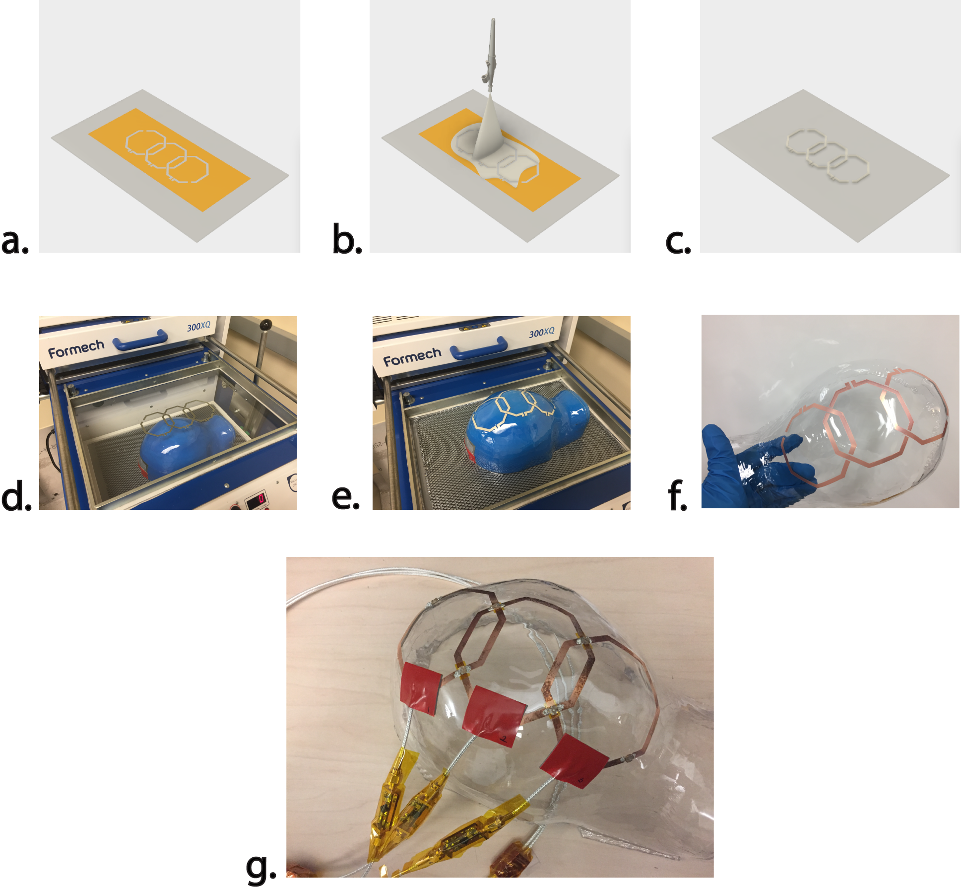
A 1/8th inch sheet of polycarbonate is masked with Kapton tape. Coil geometries are cut out of the tape with a 25 watt CO2 laser cutter. The exposed area is cleaned with isopropyl alcohol then rubbed with a 2M sodium hydroxide solution to etch the surface and promote adhesion. Aqueous silver ink is spray coated with a Badger 105 airbrush onto the substrate. Heat is rapidly applied with a heat gun to evaporate the solvent without sintering the silver particles. The Kapton mask is removed and the sheet is formed over a 3D printed head model with a Formech 300XQ vacuum forming machine.
The deformation during vacuum forming introduces micro-cracks throughout the silver traces that greatly reduce conductivity. To combat the poor conductivity, the silver traces are electroless plated with copper using a solution consisting of CuSO4, EDTA, NaOH, and formaldehyde3. Electroless plating does not require an external voltage and the plating is isotropic. Finally, rigid capacitors and Q-spoiling circuits are attached with conductive epoxy.
Vacuum forming inherently causes a large change in surface area. This can distort printed geometries thereby changing coil overlaps and inductances. The animation in figure 2 illustrates a simulation of the forming process with a printed structure. With simulation, the printed structures can be pre-distorted to yield evenly spaced coils on the 3D surface4.
Results
A receive array made of 3 octagonal, 8 cm diameter elements was constructed with the methods described above. Each coil was tuned and matched to 50 ohms at a center frequency of 123.3MHz. All coils exhibited return losses of less than -30dB. The unloaded Q of each coil was around 40. This is likely due to oxidization of the thin copper surfaces, the use of variable capacitors, and losses within the polycarbonate. We expect the Q to increase with extended copper plating times.
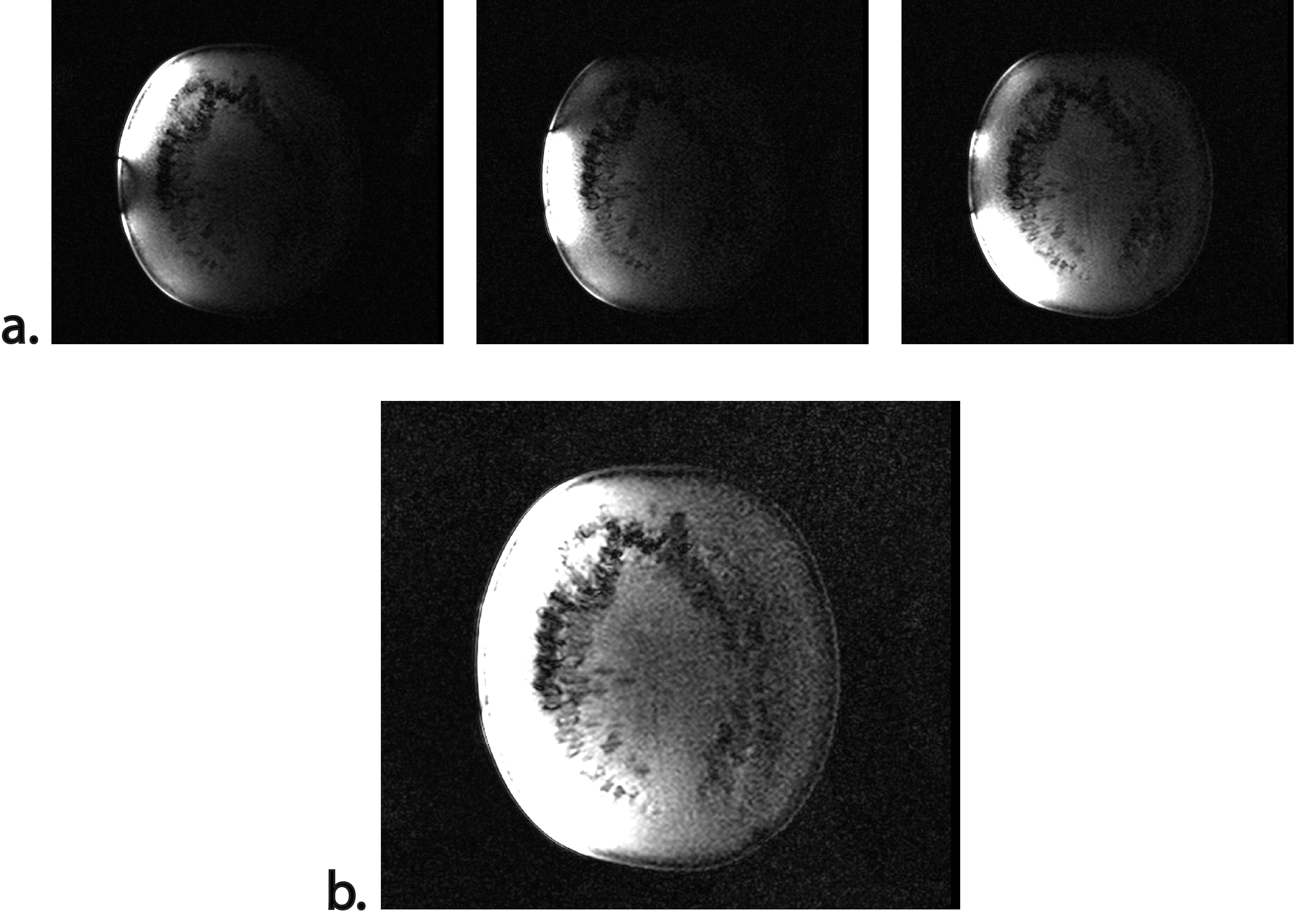
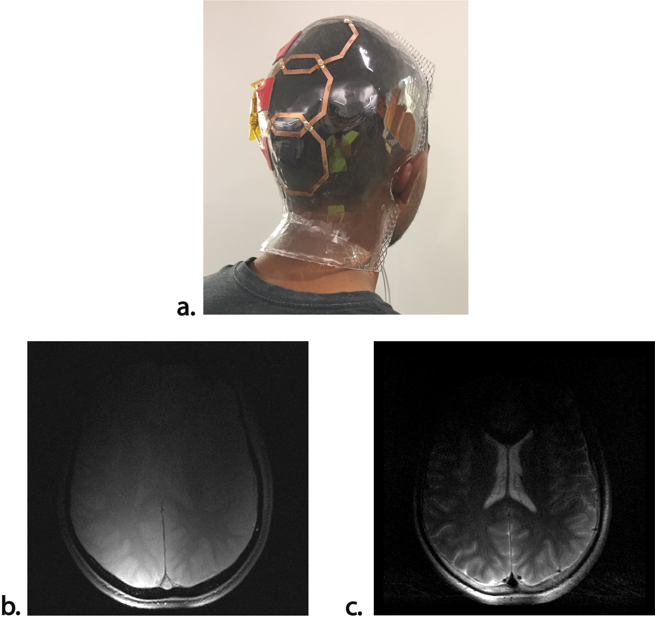
Test sequences were performed on a watermelon to verify coil decoupling and ensure safe operation. Afterwards, the coil was attached to the back of the volunteer’s head. Gradient echo (GRE - TE: 10, TR: 438) and turbo spin echo (TSE - TE: 112, TR: 3490) sequences with 0.6x0.6 mm2 resolution and 5mm slice thickness performed on a volunteer in a Siemens 3T Trio scanner. The scans reveal high SNR near the coil elements. This demonstrates potential for moving to higher channel counts spaced evenly around the region of interest.
Conclusion and Future Direction
Printed three-dimensional coils show promise for increased SNR, improved patient comfort, and reduced motion artifacts. Using our scalable manufacturing process, we built a coil array with very close proximity to the body. Future work will explore printing all tuning components and developing our simulations in order to realize the vision of digitally manufactured, custom coil sets.Acknowledgements
The authors would like to thank Nic Neath and Paul Vukovic at Formech for their generous research and technical support. Sean Doris (PARC) for help with electroless plating. Joseph Corea (UCB), James Tropp (UCB), and Jonathan Tamir (UCB) for helpful advice and scanning support. Alla Zamarayeva (UCB) and Igal Deckman (UCB) for help with ink selection and spray coating.References
- Keil, Boris, and Lawrence L Wald. “Massively Parallel MRI Detector Arrays.” Journal of magnetic resonance (San Diego, Calif. : 1997) 229 (2013): 75–89. PMC.
- Corea, J. R., Lechene, P. B., Lustig, M. and Arias, A. C. (2017), Materials and methods for higher performance screen-printed flexible MRI receive coils. Magn. Reson. Med., 78: 775–783. doi:10.1002/mrm.26399
- C.-Y. K. Chouz and Kan-Sen, "Electroless Copper Plating onto Printed Lines of Nanosized Silver Seeds," Electrochemical and Solid-State Letters 10 (3), pp. 32 - 34, 2007.
- Christian Schüller, Daniele Panozzo, Anselm Grundhöfer, Henning Zimmer, Evgeni Sorkine, and Olga Sorkine-Hornung. 2016. Computational thermoforming. ACM Trans. Graph. 35, 4, Article 43 (July 2016), 9 pages. DOI: https://doi.org/10.1145/2897824.2925914
Figures