4283
Improved transmit efficiency with Slotted Microstrip Transmission Line RF Coil Element for Ultra-high magnetic field MR Imaging1Electrical and Computer Engineering, University of Minnesota, Minneapolis, MN, United States, 2Radiology, Center for Magnetic Resonance Research, Minneapolis, MN, United States
Synopsis
Slots are introduced to the standard microstrip transmission line RF coil element, to enhance the current density and obtain better improved transmit efficiency. A prototype of such a slotted microstrip element is compared with the standard microstrip element at 297.25 MHz for 7T MR scanner to show the feasibility of the design at higher magnetic fields. A 60% improvement in the transmit efficiency and increased penetration of field into the phantom are observed experimentally. The B1+ field distribution in both transverse and sagittal plane are shown for the comparison.
Purpose
The purpose of this work is to design an efficient RF transmission line coil with increased B1+ efficiency for high SNR of the received MR signal and better image contrast with 7T and higher magnetic field MR scanners.Method
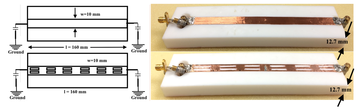
The microstrip transmission line coil element [1] is a half wavelength resonator which is foreshortened with the help of termination capacitors as shown in Fig 1. A single series capacitor or a simple pi-matching network [2] is used to match the element to input impedance. The field distribution in the microstrip element can be approximated to say that it is homogeneous. The microstrip transmission line element carries maximum current along their edges due to skin effect, and these currents are the main cause for the time varying magnetic fields (B1+ field). The transmit efficiency which is defined as the ratio of magnitude of B1+ field to the applied power (µT/√W), of these transmission line elements can be improved by increasing the current density. Like the techniques used in the past [3-4], slots are created in the microstrip line to increase the current density along the edges of the conductor. As the B1+ field strength directly depends on the current through the conductor, an improved B1+ transmit efficiency can be achieved with these slots. The feasibility of the design at high magnetic field strengths, is verified using a single channel comparison between a slotted and a standard microstrip element on a 12.7 mm thick Teflon (εr = 2.2) substrate at 297.25 MHz. A length of 160 mm, line width of 10 mm and copper cladding of 35 mm are kept same for both the elements. For the prototype of a slotted microstrip element, six set of slots of size 6 mm x 15 mm are used in two columns as shown in Fig 1. Each coil element was elevated 60 mm off the patient table and placed 12 mm away from the acrylic wall of a tall sucrose phantom having a diameter of 180 mm, εr of 58.1 and conductivity of 0.54 S/m. The tuning and matching of the elements at 297.25 MHz are verified with the network analyzer. The strong coupling of the elements with the phantom is observed by the field pickup probe measurement and with the calculation of Q-factor. To increase the SNR, a metamaterial transmission line element [5] as a receive only element, is placed on the opposite side. The microstrip elements are assumed to have zero coupling across the phantom with this metamaterial element. The transmit efficiency (in µT/√W) of each coil element is measured from the excitation flip angle induced in the phantom by an RF pulse waveform of known power. The flip angle is measured using a method called Actual Flip-angle Imaging AFI [6], a 3D dual repetition-time sequence. The AFI sequence parameters were a non-slice selective excitation with a nominal flip angle = 60 degrees, TR1=20 ms, TR2 = 120 ms, TE = 3.06 ms and a resolution of 2x2x4 mm.Results
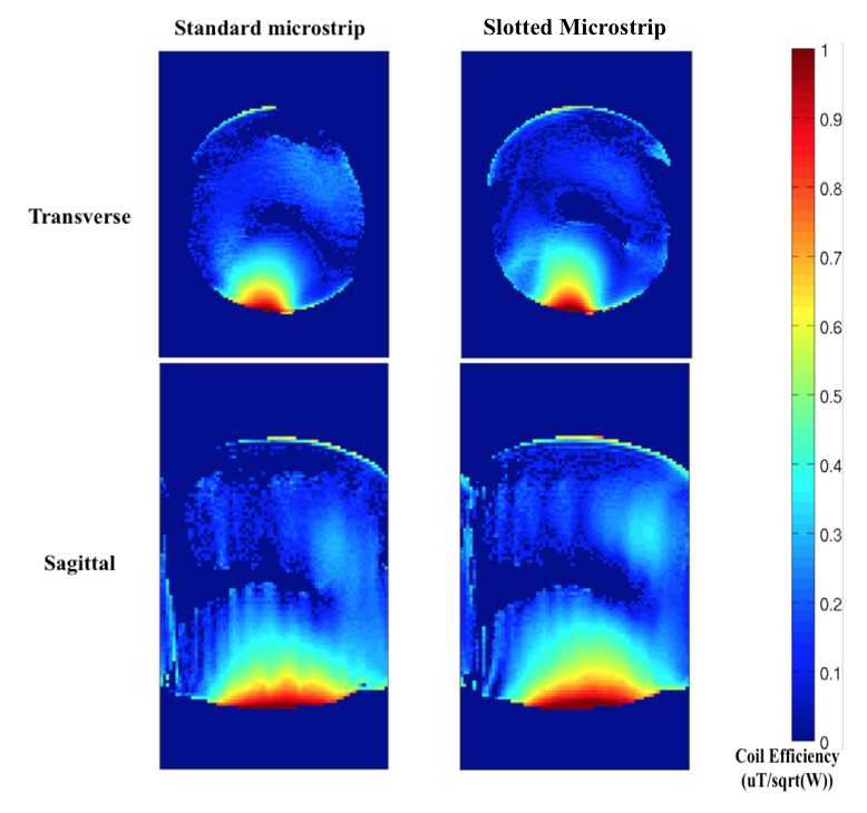
Tuning and matching conditions, coupling of the elements with the phantom, and comparison of field strength are verified on the bench. The transmit efficiency of both the standard and slotted microstrip elements are compared for the 7T MRI scanner. Fig. 2 shows a transverse and sagittal slice of the phantom for the comparison of the transmit efficiency between the standard and slotted microstrip element and Fig 3. shows the normalized transmit efficiencies of the two elements with respect to the transmit efficiency of the standard microstrip. An increase of 60% in the transmit efficiency is observed with this single channel experiment. In addition, due to the slots, narrower and more focused B1+ field distribution is observed.Conclusion
Slots are introduced in the main conductor of the standard microstrip transmission line element to increase its current density. A slotted microstrip element is compared with the standard microstrip element, to validate its performance for the high magnetic field MR scanners. The deeper penetration of the B1+ field into the tissue or phantom from the RF coil is observed which improves the SNR of the received MR signal and provides better image quality in the MR imaging. A 60% improvement in the transmit efficiency is obtained without any additional cost or loss in performance and this can be easily implemented in any other elements that uses microstrip technology like loop coils or dipoles.Acknowledgements
This work is supported in part by the National Institute of Health (NIH) NIH-EB0006835, in part by S10 RR026783 “Multichannel Transmit Frontend for 7 Tesla” WM KECK Foundation and in part by University of Minnesota.References
[1] Zhang, X., Ugurbil, K. and Chen, W., 2003. Journal of Magnetic Resonance, 161(2), pp.242-251
[2] Sohn, S.M., DelaBarre, L., Vaughan, J.T. and Gopinath, A., 2012, June. In Microwave Symposium Digest (MTT), 2012 IEEE MTT-S International (pp. 1-3). IEEE
[3]Sohn, S.M., DelaBarre, L., Gopinath, A. and Vaughan, J.T., 2014. IEEE transactions on microwave theory and techniques, 62(8), pp.1784-1789
[4] Son, H.W., Cho, Y.K. and Yoo, H., 2014. A novel RF resonator for human-body MRI at 3 T. Journal of the Korean Physical Society, 64(6), pp.813-816
[5] Panda, V et al., IEEE J-ERM 2017 (under review)
[6] Yarnykh, V.L et al., 2007. Magnetic resonance in Medicine
Figures