4279
Evaluation of Egyptian axe dipole antenna as an array element for head imaging at 7T MRI1Radiology Department, C.J. Gorter Center for High Field MRI, Leiden University Medical Center, Leiden, Netherlands
Synopsis
In this abstract we propose a new antenna design
as a transmit array element for proton head imaging at 7T that combines a small
feeding dipole that is capacitively coupled, as a so-called ‘indirect’ or
‘passive’ feed, to an ‘Egyptian’ axe dipole. B1+ and SAR
efficiency of the proposed antenna have been compared numerically with a
conventional dipole antenna of the same length. A head array consisting of eight
antenna elements has been constructed and tested. This array element offers a
large reduction in SAR compared to equally sized linear dipoles while
maintaining their B1+ profile as well as reducing the
impact of antenna loading on the resonance frequency.
Introduction
Neuroimaging at 7 Tesla is complicated by interferences that occur in the B1+ field as a result of the relatively short wavelength of the RF transmit field compared to the dimensions of the human head1. RF shimming by controlling the relative phases of individual transmit elements in a transmit array allows for an increased homogeneity of the transmit field in the human head compared to a standard circularly polarized excitation2,3. With the increased availability of multi-channel transmit systems, many array designs for neuroimaging in UHF-MRI have been proposed2,4,5.
In this abstract we propose a new design for a dipole antenna array for proton head imaging at 7T that combines a small feeding dipole that is capacitively coupled, as a so-called indirect or passive feed, to an ‘Egyptian’ axe dipole (EAD)6.
Methods
The EAD antenna was printed on a 0.5 mm thick RT DUROID 6035HTC substrate (ɛr=3.5 and tanδ=0.0013). The primary dipole element with one tuning inductor in the middle was fabricated on one side while a shorter dipole antenna, which acts as the feeding element, was fabricated on the other side of the substrate (Fig. 1). The total length of the feeding dipole was 70 mm and the length of the EAD passive element was 145 mm.
Electromagnetic simulations were carried out in CST Microwave Studio (CST, Darmstadt, Germany). B1+ and SAR10g distributions were simulated for a conventional 15 cm straight dipole and for the EAD antenna. The position of the tuning inductor on the conventional dipole was optimized for transmit efficiency.
S11 sensitivity of a single antenna on the load proximity was measured on Vector Network Analyzer (VNA) and a rectangular agarose phantom (ɛr=80 and σ=0.4 S/m) at distances from 20 mm to 60 mm.
Eight identical antennas were fabricated and fixed on a plastic cylindrical support with an outer diameter of 26 cm. Each antenna was placed onto the cylinder using a 1 cm thick foam support. A realistic loading phantom (εr=50 and σ=0.6 S/m) was centered inside the holder with the antennas.
Measurements were performed on Philips Achieva 7T scanner. In vivo scan were performed on a brain of volunteer with a low tip-angle 3D gradient echo sequence. The sequence parameters were FoV=240x180 mm, slice thickness 3.75mm, FA=10o, TE/TR=2/4 ms.
Results
Figure 2 shows simulated B1+ profiles of the EAD antenna and conventional dipole. The simulated B1+ field data was normalized to 1W of input power (Fig. 2(c)) and to max SAR10g (Fig. 2 (d)). In both cases the EAD antenna exhibits slightly higher B1+ efficiency than straight dipole antenna. Figure 3 shows the antenna’s matching sensitivity on the separation distance from the phantom. Figure 4 shows RF shimming with the array when the B1+ fields was focused in three region of interest (ROI) different positions. Figure 5 shows in vivo scans of a human brain with RF shimming with respect to two spatially different regions of interest (Fig. 5 (a) and (b)).
Discussion
Because of the arcs at the end of a passive element of proposed EAD antenna, B1+ longitudinal coverage is slightly longer compared to the straight linear dipole due to a longitudinally more even current distribution on the EAD antenna. A large reduction in SAR compared to equally sized linear dipole while maintaining B1+ efficiency with respect to input power has been observed. The relatively low sensitivity of the S11 on the distance from a phantom ensures low sensitivity of the array on the head size and head position inside an array.
Conclusion
The EAD array element design offers a reduction in SAR compared to equally sized linear dipoles while maintaining B1+ efficiency. RF shimming on a phantom and in vivo also has been demonstrated, indicating the potential of this element for transmit arrays for neuroimaging.
Acknowledgements
This work was funded by the ERC NOMA-MRI grant, number 670629.References
1. Vaughan JT, Garwood M, Collins CM, et al. 7T vs. 4T: RF power, homogeneity, and signal‐to‐noise comparison in head images. Magn Reson Med 2001; 46. doi: 10.1002/mrm.1156.2. Adriany G, Moortele P-FV de, Wiesinger F, et al. Transmit and receive transmission line arrays for 7 Tesla parallel imaging. Magn Reson Med 2005; 53. doi: 10.1002/mrm.20321.
3. Ibrahim TS, Lee R, Baertlein BA, Abduljalil AM, Zhu H, Robitaille P-ML. Effect of RF coil excitation on field inhomogeneity at ultra-high fields: a field optimized TEM resonator. Magn Reson Imaging 2001; 19:1339–1347.
4. Avdievich N, Hoffmann J, Shajan G, Pfrommer A, Giapitzakis IA , Scheffler K, Henning A. Evaluation of transmit efficiency and SAR for a tight fit transceiver human head phased array at 9.4 T. NMR Biomed. 2017;30:n/a-n/a. doi: 10.1002/nbm.3680.
5. Hong S-M, Park JH, Woo M-K, Kim Y-B, Cho Z-H. New design concept of monopole antenna array for UHF 7T MRI. Magn Reson Med 2014;71:1944–1952.
6. Zivkovic I and Webb A. Design of an Egyptian axe dipole antenna for 7T MRI. 34th Annual Scientific Meeting Barcelona, Spain; ESMRMB 2017.
Figures
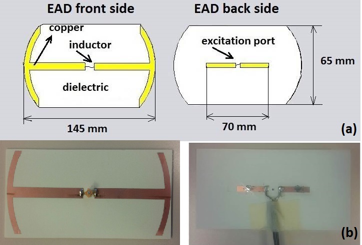
Figure 1. Geometry of the Egyptian axe dipole antenna (a) and photos of the fabricated antenna (b).
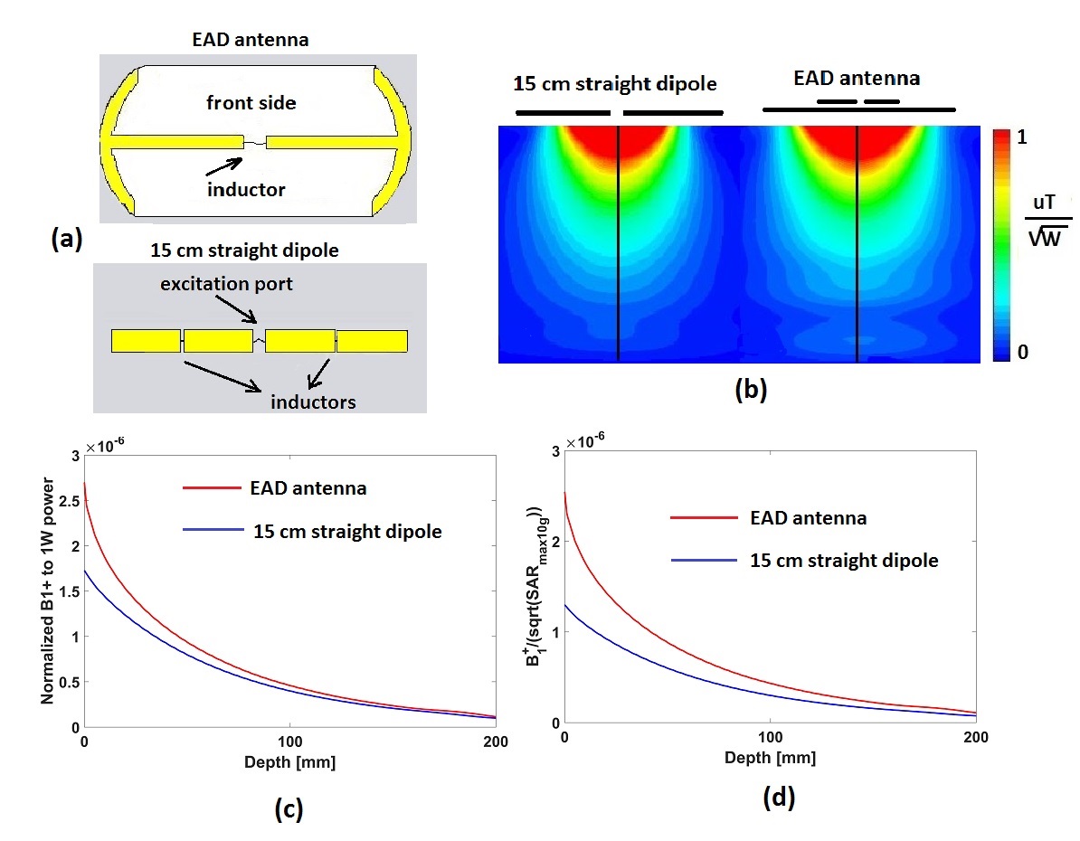
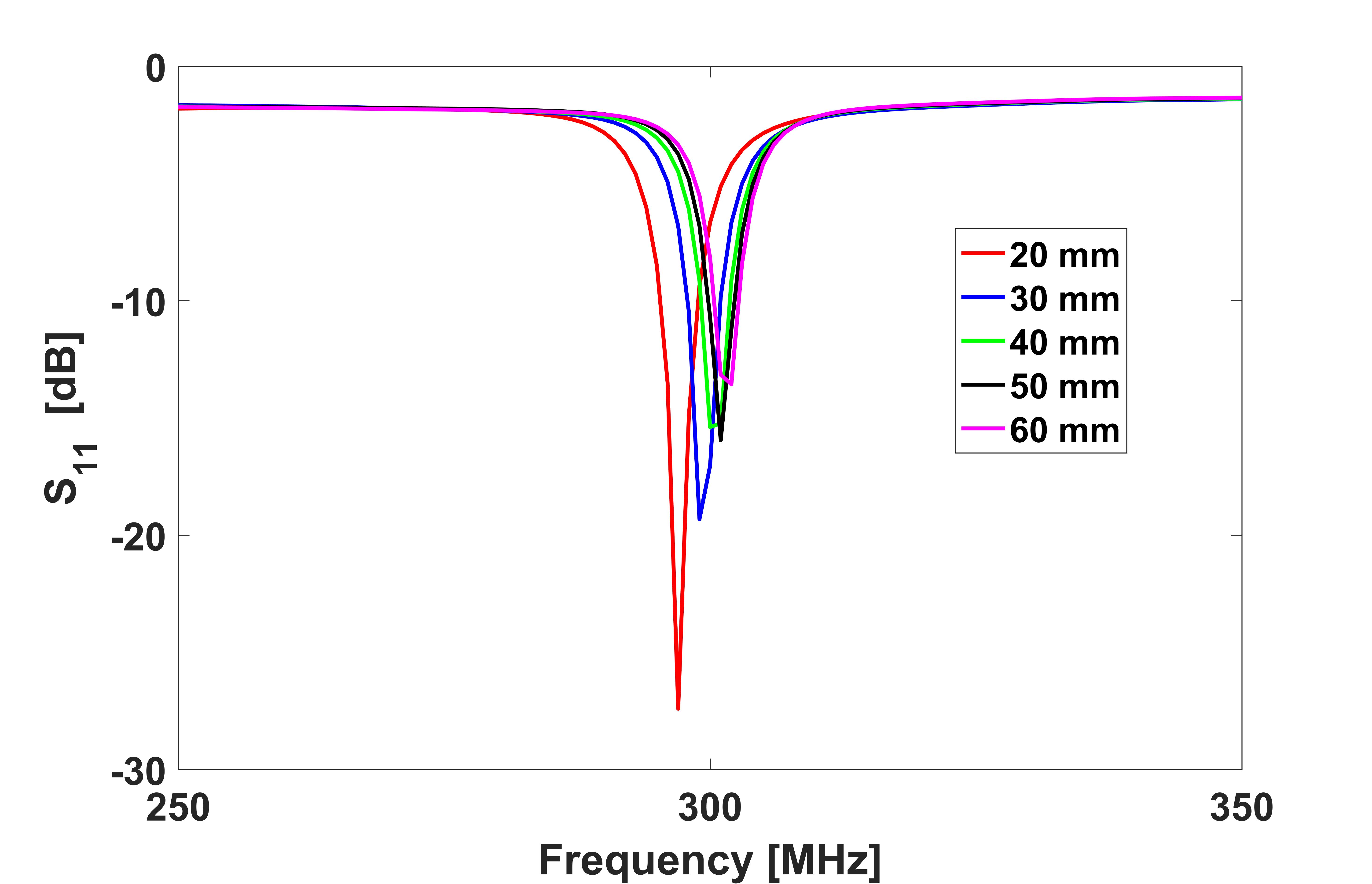
Figure 3. Measured S11 of fabricated EAD antenna for different distances to the phantom.
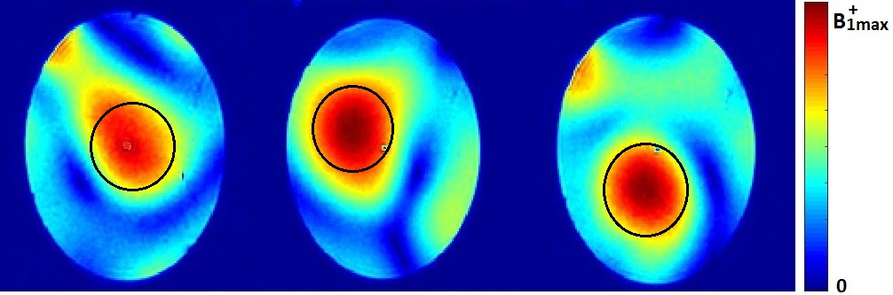
Figure 4. RF shimming with an array consisting of eight fabricated antennas placed on a cylindrical holder around an elliptical head phantom. Three different region of interest (ROI, black circles) were chosen and the RF shimming, aiming for the highest signal intensity in a ROI, was performed.
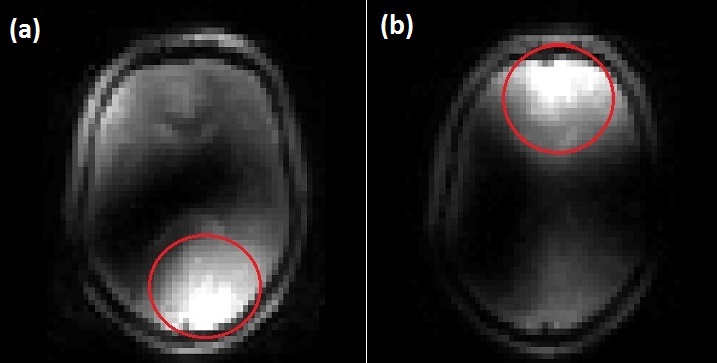
Figure 5. In vivo scan of a volunteer’s brain with two different regions chosen for RF shimming