4277
High-accuracy SNR calculation for multi-channel receiver coils with electromagnetic simulation considering coil-component losses1Research & Development Group, Hitachi, Ltd., Tokyo, Japan, 2Healthcare Business Unit, Hitachi, Ltd., Tokyo, Japan
Synopsis
Electromagnetic simulation is a powerful tool to evaluate optimal radio frequency (RF) coil design without costly prototypes. However, RF receiver coils have accessory circuits, such as decoupler circuits, that make it difficult to reflect accurate coil loss. This leads to calculation error which can be non-negligible even in high static magnetic fields, especially for small loop coils. We measured the coil-component losses and took them into account for the simulation to calculate the signal-to-noise ratio (SNR). The calculated SNR had less than 5% error when compared to SNR measured with a 1.5-T MRI scanner for 10-channel receiver-array coils, confirming high accuracy of multi-channel SNR simulation.
Introduction
Recent increase in the number of receiver channels enables high-density RF array coils. For RF receiver coils with a large number of channels, electromagnetic (EM) simulation is a powerful tool to evaluate optimal design without costly prototypes. However, coil loss can become comparable to sample loss as the loop-size decreases, even in high static magnetic fields.1 It is important to include accurate coil loss to the simulation model to calculate the signal-to-noise ratio (SNR) with high accuracy using EM simulation.2 However, RF receiver coils have accessory circuits, such as decoupler circuits, that make it difficult to reflect accurate coil loss. Therefore, large estimation error of coil loss is an issue for SNR simulation.
In this study, we assessed the coil loss of each coil component through measurement and incorporated each loss to the simulation model. We applied this to 10-channel (ch) array coils and evaluated SNR calculation error by comparing the simulated SNR to that measured using a 1.5-T MRI scanner.
Methods
Simulation
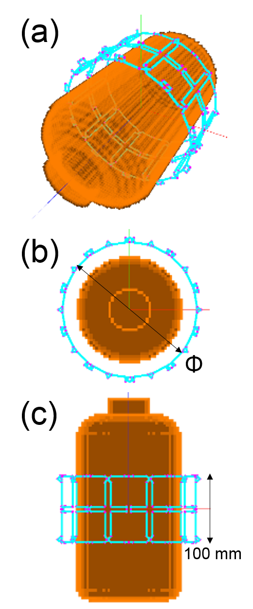
We used an in-house built EM simulator based on method of moments3 which enables sub-millimeter overlap adjustments. Figure 1 shows the 10-ch array model. Neighbor channels were decoupled with overlap,4 and next-neighbor channels were decoupled with inductive coupling. Preamp decoupling4 was applied to all channels with preamps of 2 Ω input impedance. Three types of coil diameters, Φ178, 203, and 254 mm, were investigated with a cylindrical phantom of Φ165 mm (cell size (4 mm)3, σ=0.58 S/m, εr=86). Coil loss of passive and active decoupling circuits and decoupling inductors were assessed from unloaded Q measurements of a loop coil with/without the components. Capacitor loss was assessed from the manufacture’s datasheet. Residual loss was assessed as the conductor loss including solders. The noise correlation matrix was calculated as $$\Psi^s_{ij} = \frac{R_{ij}}{\sqrt{R^\ast_{ii}R_{jj}}},$$ $$R_{ij} = \sigma\int_V \vec{E_{i}}(x,y,z)\cdot\vec{E_{j}}^{\ast}(x,y,z)dV,$$ $$R_{ii} = \sigma \left( 1+\frac{1}{Q_{ui}/Q_{li}-1} \right) \int_V \left| \vec{E_{i}}(x,y,z) \right|^2 dV$$ (where $$$V$$$: volume of phantom, $$$\vec{E_i}$$$: electric field of ch $$$i$$$, $$$Q_{ui}/Q_{li}$$$: ratio of unloaded to loaded Q of ch $$$i$$$). The SNR was calculated as $$$SNR_{OPT} = \sqrt{{\bf {S^\ast_s \cdot (\Psi^s})^{-1}\cdot {}^t\!S_s}}$$$, where $$${\bf S_s}$$$ is the sensitivity of all channels.4
Measurement
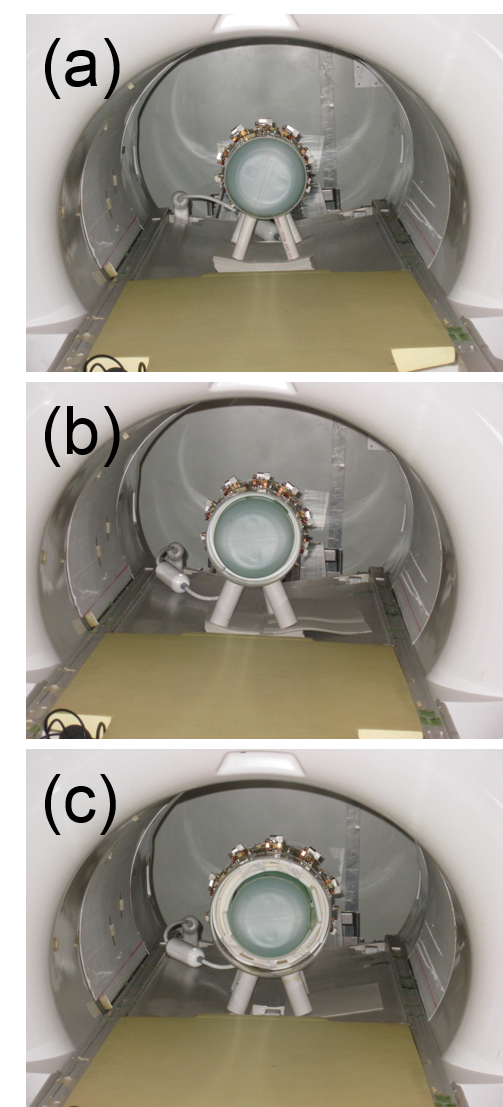
We fabricated three types of 10-ch receiver coils in accordance with the simulation. The SNR was measured using a 1.5-T MRI scanner (Hitachi Ltd., Japan). Figure 2 shows the experimental setup including the coils and phantom (NiCl2 0.2%, NaCl 0.25%). A central axial slice was scanned with a 2D GrE sequence. The noise correlation matrix was measured as $$$\Psi^m_{ij} = (\Sigma^M_{k=1} n_{i,k}n^\ast_{j,k})/M$$$ (where $$$n_{i,k}$$$: noise of ch $$$i$$$ at pixel $$$k$$$, $$$M$$$: number of pixels). The SNR was calculated as $$$SNR_{OPT} = \sqrt{{\bf {S^\ast_m \cdot (\Psi^m})^{-1}\cdot {}^t\!S_m}}$$$, where $$${\bf S_m}$$$ is the signal of all channels.4
SNR evaluation
1) Signal intensity errors: $$$\sqrt{{\bf {S^\ast_s \cdot {}^t\!S_s}}}$$$ and $$$ \sqrt{{\bf {S^\ast_m \cdot {}^t\!S_m}}}$$$ were compared.
2) Noise correlation errors: SNROPT calculated with noise correlations $$${\bf {\Psi^s}}$$$ and $$${\bf {\Psi^m}}$$$ for the same signal ($$${\bf S_s}$$$) were compared.
3) SNR error: First, the estimated calculation error was evaluated as the root-sum-square of independent errors from 1) and 2) according to error propagation. Second, SNROPT of simulation and measurement were compared for confirmation.
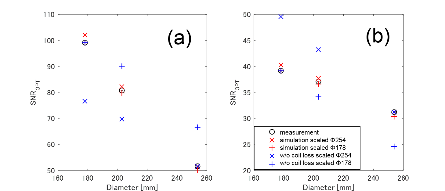
[For all evaluations]: Two region of interests, ROI A: Φ146.5 mm (75% area) and ROI B: Φ30 mm (center region), were analyzed. Simulated results were scaled to measured results (at Φ254 and 178 mm, respectively), and the maximum error was evaluated.
Results
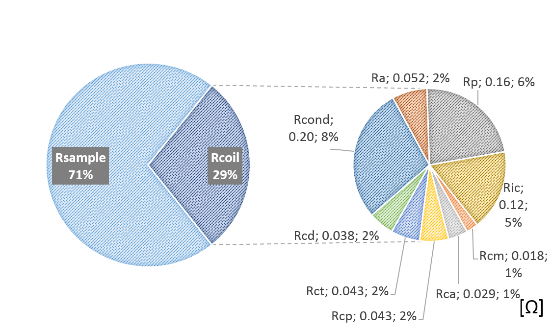
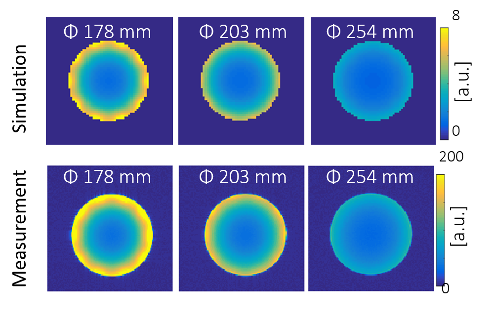
Figure 3 shows the measured coil-component losses. The percentage of losses are shown for the Φ178-mm coil. The simulated ratios of Qu to Ql (Qu/Ql) were 2.7, 1.9, and 1.4 for Φ178, 203, and 254 mm, respectively, while those of the measurement were 3.5, 2.3, and 1.5. The maximum signal intensity error was 4.1% and maximum noise correlation error was 2.4%. Therefore, the SNR calculation error was estimated to be 4.8%. Figure 4 shows SNROPT maps of the simulation and measurement. The simulation results describe well the SNR change in the center and periphery as the coil loss and sample loss ratio (Qu/Ql) changed. Figure 5 shows SNROPT analyzed at ROIs A and B. The maximum error was 3.1% within the estimated error range of 4.8%.Discussion
We investigated well decoupled arrays with sub-millimeter overlap adjustments. Further investigation is needed for arrays with non-negligible coupling. The coil-component-loss assessment and SNR calculations can also be applied to other EM simulators such as FDTD based simulators. However, careful mesh settings may be needed for accurate Qu/Ql; hence, accurate SNR.Conclusion
Coil-component loss including decoupler circuits were assessed. Calculated SNR for 10-ch arrays at 1.5 T had less than 5% error, confirming high accuracy of multi-channel SNR simulation even with non-negligible coil loss.Acknowledgements
No acknowledgement found.References
- Farivar R, et al. Dense, Shape-Optimized Posterior 32-Channel Coil for Submillimeter Functional Imaging of Visual Cortex at 3T. Magn Reson Med. 2016;76:321-328.
- Kumar A, et al. Noise Figure Limits for Circular Loop MR Coils. Magn Reson Med. 2009;61:1201-1209.
- Ochi H, et al. Calculation of Electromagnetic Field of an MRI Antenna Loaded by a Body. In: Proc SMRM 11th Ann Mtg. 1992:4021.
- Roemer PB, et al. The NMR Phased Array. Magn Reson Med. 1990;16:192-225.
Figures