4274
8-channel whole-brain center-fed dipoles with quadrature frontal loops coil array1LIFMET, EPFL, Lausanne, Switzerland, 2CIBM-AIT, EPFL, Lausanne, Switzerland, 3Department of Radiology, University of Lausanne, Lausanne, Switzerland, 4Department of Radiology, University of Geneva, Geneva, Switzerland
Synopsis
To achieve highly efficient whole-brain coverage, including cerebral cortex and cerebellum, a single-row 8-channel RF coil array, built with center-fed dipoles, was investigated. B1+ maps and anatomical images were acquired on the human brain for RF phases optimized over the whole-brain and high transmit field performances were shown in both cerebral cortex and cerebellum with good homogeneity. Functional MRI data was acquired on auditory cortices and demonstrated higher robustness compared to a commercial volume coil.
Introduction
Dipole antennas were proposed as an alternative to loop coils or microstrips as they were shown to have better field uniformity and could provide larger longitudinal coverage, at 7T [1]. Aiming for both cerebral cortex and cerebellum coverage in the human brain, we investigate the capabilities of a single-row 8-channel RF coil array, built with center-fed dipoles.Methods
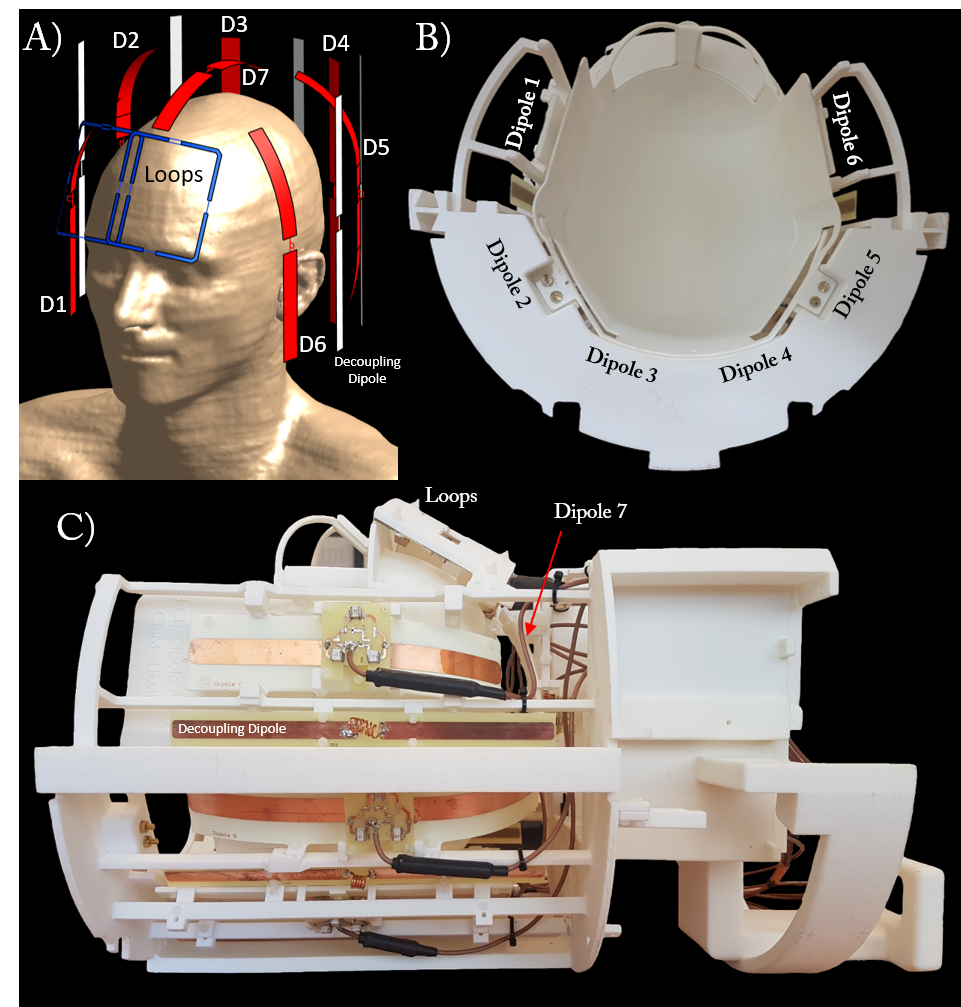
Coil array design: Six center-fed dipoles were placed around the occipital and temporal lobes of the brain (inter-element distance≈75mm) while a seventh center-fed dipole was placed around the parietal lobe and aligned in anterior-posterior direction (Fig.1). The dipoles were copper-printed (35μm-thickness,15mm width) on flexible PCB and their lengths were varied from 158.5mm to 230mm according to the shape of the brain. A decoupling method based on magnetic wall approach [2] was applied to ensure sufficient isolation between dipoles. Two loops placed at the frontal lobe were driven with a single transmit channel. Conformal housing was designed (Solidworks,DassaultSystems,France) and 3D-printed (EOSINT P395,EOS,Germany) in nylon (EOS,PA2200). Finite-difference time-domain (FDTD) simulations were performed on Sim4Life 3.4 (ZMT, Switzerland) on a virtual family human model [3] for the exact model of the coil array.
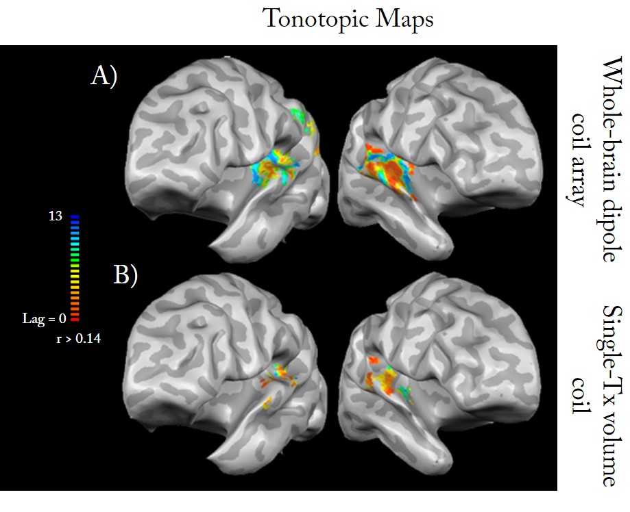
fMRI paradigm [4]: A subject with hearing loss and tinnitus (permanent ringing percept without physical sound) listens passively to two runs of progressions of pure tones bursts (88-8000Hz,half-octave steps), repeated 15 times over a 8-min run, and presented in ascending (88 to 8000Hz) or descending (8000 to 88Hz) order. Functional data were preprocessed (motion correction,alignment with the structural in Talairach space) and analyzed with cross-correlations analysis in BrainVoyager QX (2.8.4,Brain Innovation,Maastricht). Resulting correlations (tonotopic) maps were averaged and projected on segmented inflations of the structural images (corrected for field inhomogeneities and normalized to the Talairach space) and compared with similar correlation maps acquired with a standard volume coil (RAPID Biomedicals,Germany).
MR experiments: B1+-maps [5] and anatomical images from male volunteers were acquired using a Magnetom 7T MR scanner with an 8x1kW RF-amplifier (Step 2.3,Siemens,Erlangen,Germany). Optimal RF-phases were calculated with a particle-swarm-optimization method [6] and the following sequences were used: 3D-Turbo-Spin-Echo (0.8x0.8x0.8mm3,TR/TE=2000/120ms,TA=10min,GRAPPA=2,Averages=1), 3D-MP2RAGE [7] (0.6x0.6x0.6mm3,TR/TE=5500/1.67ms,TA=10min08s,GRAPPA=3). Bold signal was acquired for RF phases optimized on the auditory cortex with a 2D-EPI sequence (1.5x1.5x.1.5mm3,TR/TE=2000/25ms,GRAPPA = 2,30 slices,240 volumes,interleaved even).
Results
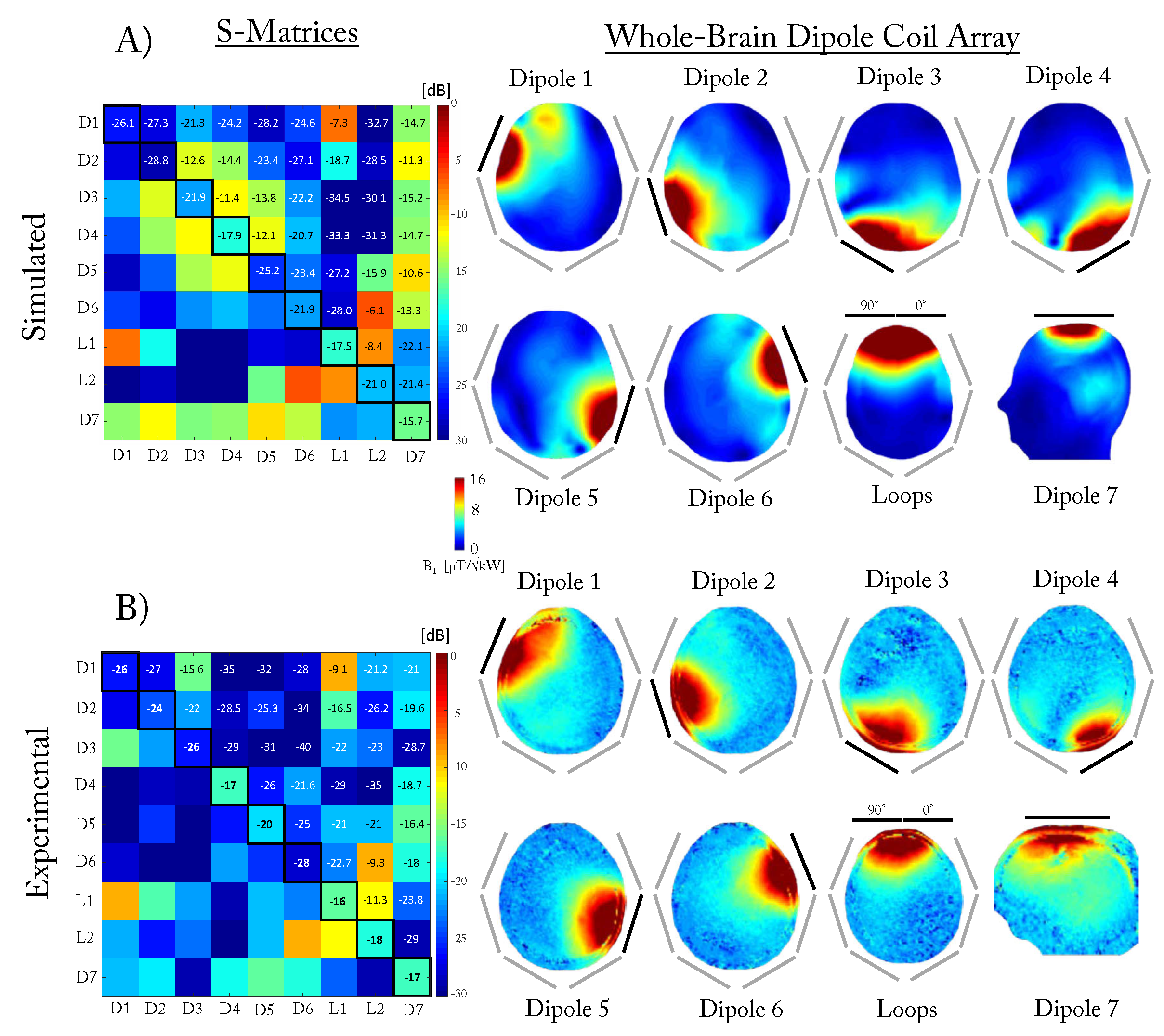
Measured S-matrix for the whole-brain center-fed dipoles and frontal loops coil array demonstrated coupling values between neighbors and next neighbors below -15dB for all the dipoles (Fig.2B). Similar reflection coefficients were achieved for the FDTD simulated coil array, but higher coupling was observed between dipoles 2, 3 and 4 and between the dipole 7 with all the other dipoles (Fig.2A). The highest coupling in both measurements and simulations (>-9dB) occurred between the dipoles 1 and 6, and the two loops. Individual measured and simulated B1+-maps (Fig.2A-B) were similar and indicated a uniform transmit field distribution for the dipoles except for the dipole 1 which was visibly coupled to the closest loop.
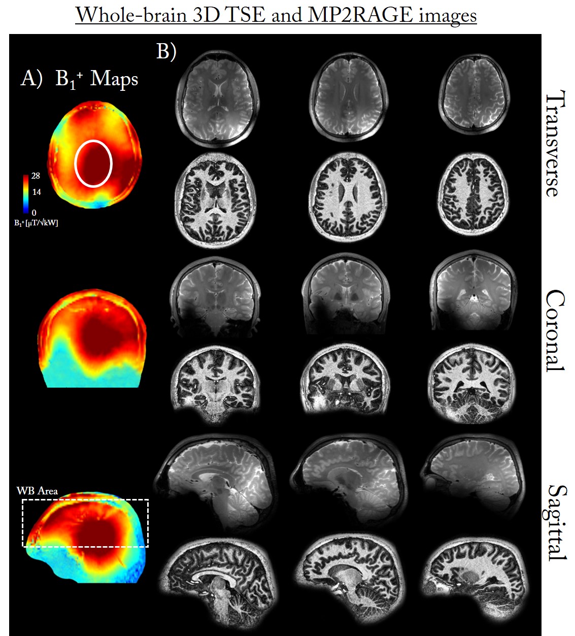
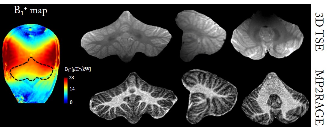
B1+ maps and anatomical images: With RF-phases optimized in mid-brain transverse slice, a mean B1+ of 28±2.3µT was measured over the shimmed ROI (Fig.3A,white solid line) while over a 3D volume encompassing the whole cerebral cortex (Fig.3A,white dashed rectangle), a mean B1+ of 23.2±3.7µT was achieved for 1kW input power at the coil plug. The high-resolution 3D-TSE images demonstrated a whole-brain coverage with relatively good homogeneity across the slices in the three orientations (Fig.3B). With RF-phases optimized in cerebellum for maximal homogeneity, a mean B1+ of 20.1 ± 2 $$$\mu T/\sqrt{kW_{input}}$$$ was measured over a 3D volume encompassing the whole cerebellum (Fig.4). In both cases, the high-resolution MP2RAGE (0.6mm-iso) images demonstrated high homogeneity across multiple slices.
fMRI results demonstrated similar functional organization (mirror-symmetric tonotopic gradients) in both datasets. Differences between hemispheres are due to the hearing deficits (frequency over-representations). However, at similar threshold, data was more robust for the whole-brain center-fed dipoles and frontal loops coil array (Fig.5).
Discussion and Conclusion
Whole-brain coverage with good homogeneity, including cerebral cortex and cerebellum was demonstrated in MR images with the 8-channel center-fed dipoles and frontal loops coil array. Moreover, high B1+ could be achieved in any region of the head with RF-phases optimization which contributed to the higher robustness of fMRI results in auditory cortices compared to a volume coil. With measured coupling values lower than -15dB, the magnetic wall approach to decouple neighbor dipoles was demonstrated to be highly efficient while no visible drawback on RF shimming quality was observed. We conclude that a combination of seven center-fed dipoles and frontal loop coils for an efficient coil array is feasible and allows flexible coverage of the whole brain at 7T.Acknowledgements
This study was supported by Centre d’Imagerie Biomedicale (CIBM) of the UNIL, UNIGE, HUG, CHUV, EPFL and the Leenaards and Jeantet Foundations.References
[1] Raaijmakers AJE et al. Magn. Reson. Med. 2011; 66: 1488-1497
[2] Yan X et al. Appl. Magn. Reson. 2015; 46: 59-66
[3] Gosselin MC et al. Phys. in Med. and Biol. 2014; 59(18)
[4] Da Costa S et al. J. Neurosci. 2011
[5] Eggenschwiler F et al. Magn. Reson. in Med. 2012; 67: 1609-1619
[6] Clement J et al. Proc. ESMRMB, 2015
[7] Marques JP et al. NeuroImage, 2010; 49: 1271-1281
Figures