4273
Application of Asymmetric Mode Ladder Resonators for Improved Efficiency of Individual Elements in Transceive Arrays1POLARIS, Academic Radiology, University of Sheffield, Sheffield, United Kingdom, 2GE Healthcare Inc., Aurora, OH, United States
Synopsis
Conventional vest coil designs typically have less homogeneous excitation and higher SAR than volume resonators. Here we introduce a hybrid of a ladder resonator and transceiver array to provide the individual benefits of both. A network theory approach is presented for the calculation of tuning values. Simulation and measurement of a two ladder element transmit array with three loop sections each is demonstrated. Additionally, the six individual loop sections are employed as separate receive coil elements. Improved transmit homogeneity and lower specific absorption ratio is observed in simulation against a comparable transmit vest coil array. The tuning and transmit field homogeneity is verified through measurement of imaging performance.
Background
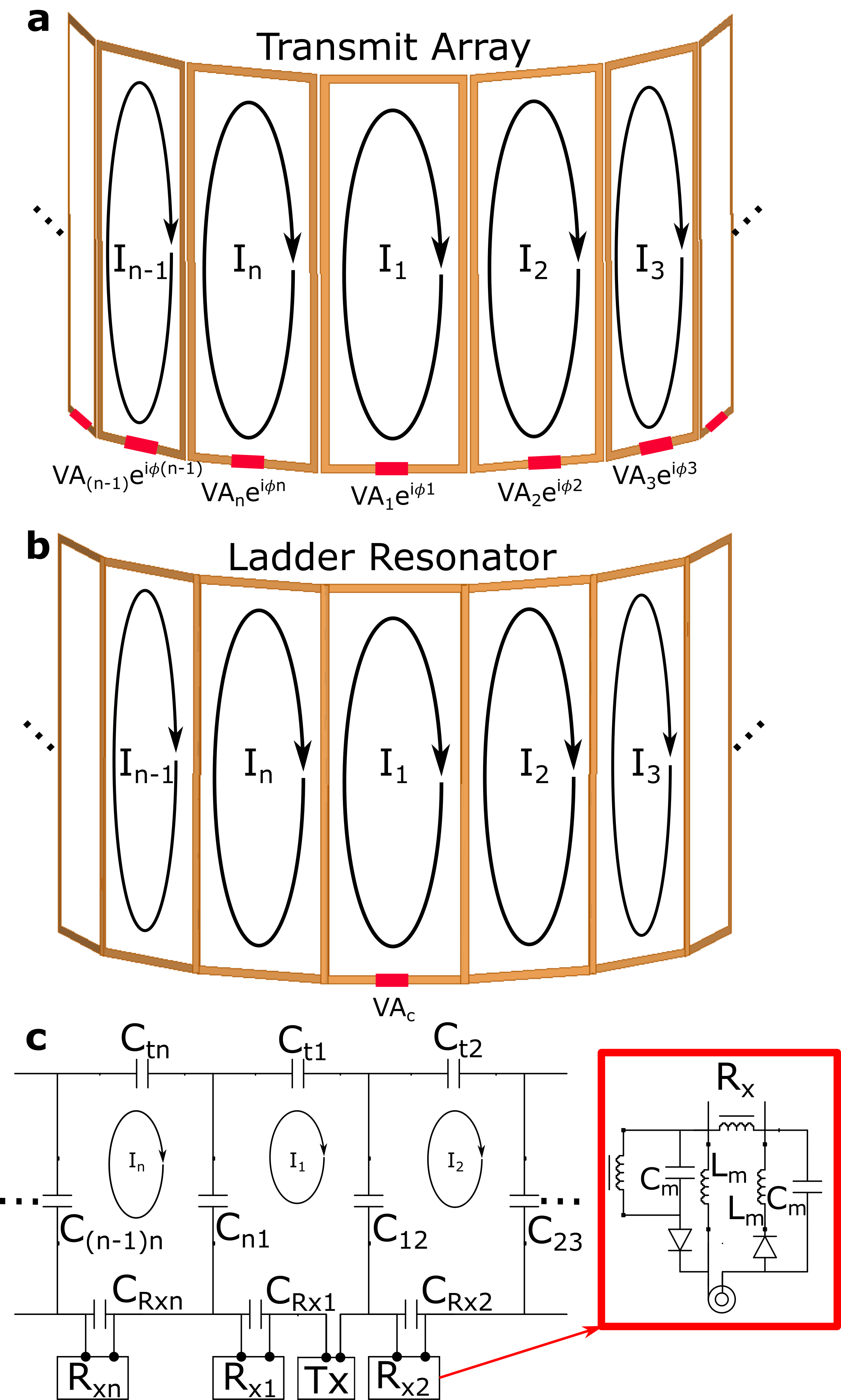
A continual research area of MR radio-frequency (RF) coil engineering has been the efficient and homogeneous generation of the circularly polarized field (B1+) for MR excitation in diverse applications. Simplified versions of transmit arrays and ladder resonators are diagrammed in Figure 1a/b, respectively. Transmit arrays have distinct elements with separate voltage excitations achieved by power/phase division from a single power source1,2, or via separate variable sources3,4. Ladder resonators have a continuous conducting structure. The birdcage coil is the most commonly used volume ladder resonator in MR5,6, and forms a periodic structure. Whereas, the half-birdcage7 and two-dimensional ladder resonators8 are non-periodic. Ladder resonators current/phase variation is optimized for homogeneous excitation but, they are more sensitive than transmit arrays to geometry and loading variation.Purpose
To investigate the combination of ladder resonator structures as transceive arrays for improved excitation homogeneity and specific absorption ratio (SAR). The work is highlighted with the potential application of thoracic coils as used for proton and X-nucleus imaging (e.g. inert gas lung MRI).Methods
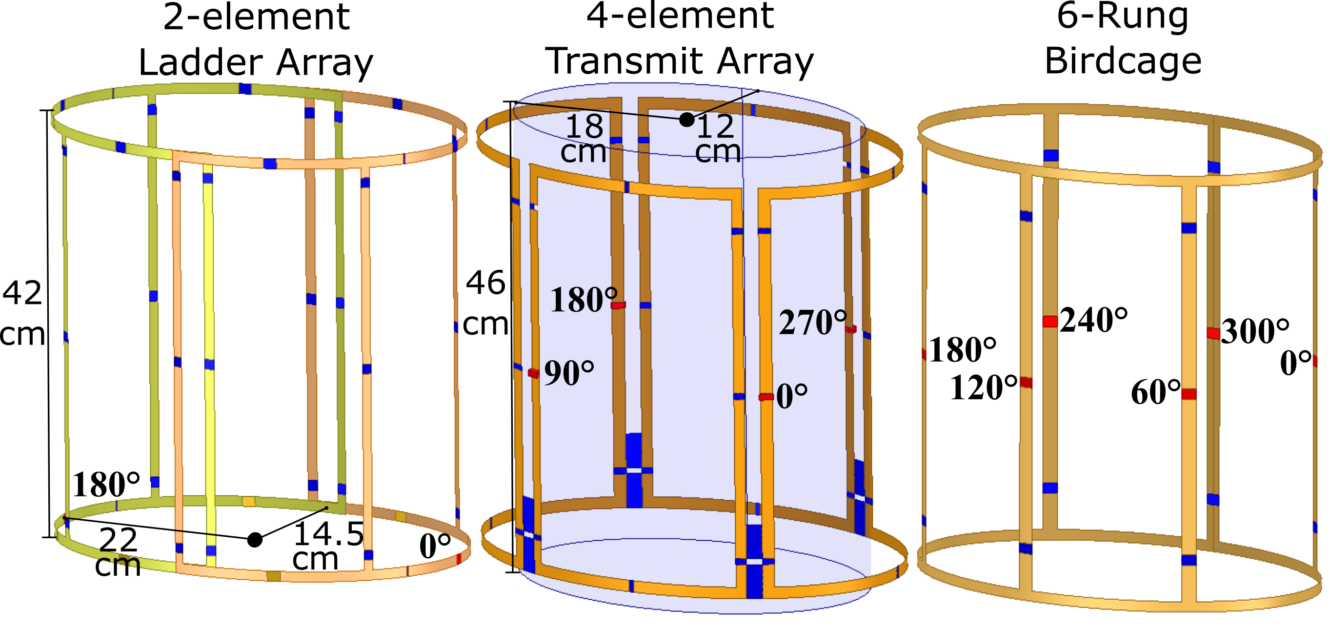
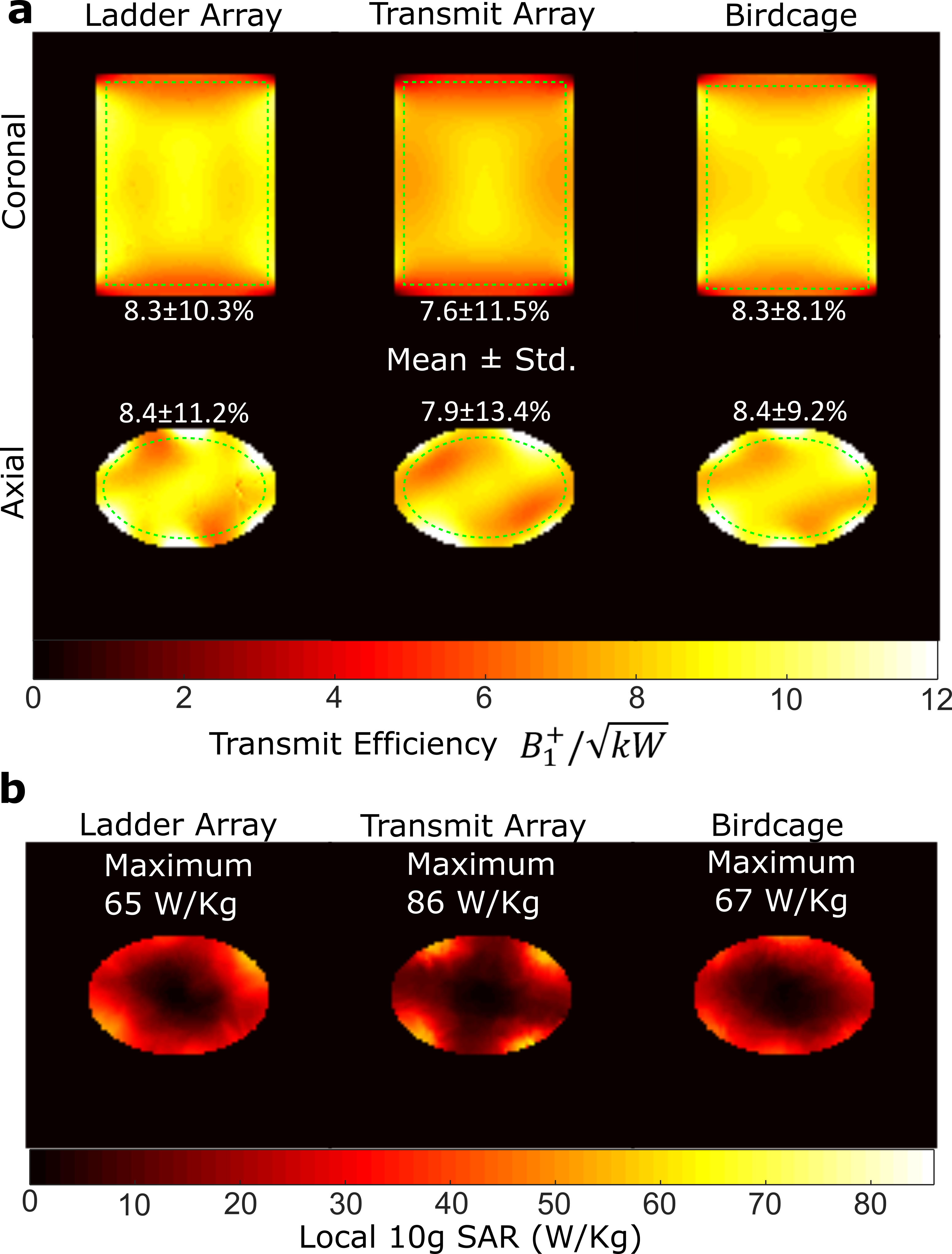
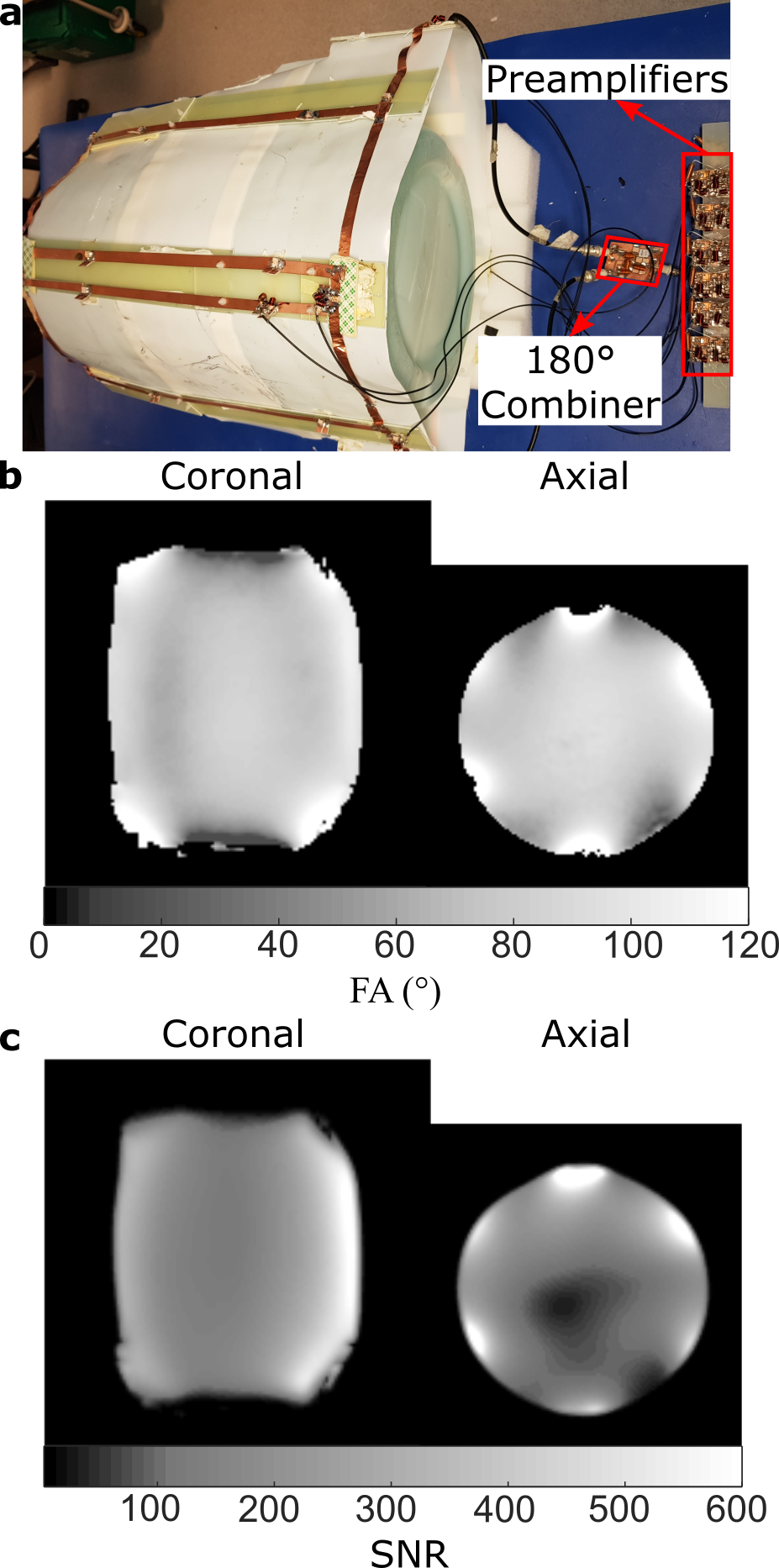
For the n-loop ladder resonator shown in Figure 1b, with circuit diagram in Figure 1c, the lumped current distribution can be generalized as$$\begin{bmatrix}I_{1}e^{i\phi1}\\:\\I_{1}e^{i\phi n}\end{bmatrix}=\begin{bmatrix}Z_{11}+Z_{t1}+Z_{CRx1}+\sum_{m\neq{1}}^{}Z_{c1m} & .. & Z_{n1}-Z_{c1n}\\: & \diagdown & {} \\Z_{1n}-Z_{c1n} & {} & Z_{nn}+Z_{tn}+Z_{CRxn}+\sum_{m\neq{n}}^{}Z_{cnm}\end{bmatrix}^{-1}\begin{bmatrix}A_{c}V\\{:}\\0\end{bmatrix}$$where $$$Z_{nn}$$$ and $$$Z_{mn}$$$ are inherent to the coil geometry, while $$$A_{c}{V}$$$ is the source excitation. The self ($$$Z_{tn}$$$) and mutual ($$$Z_{cmn}$$$) impedance tuning is accomplished with the lumped tuning capacitors ($$$C_{tn}$$$,$$$C_{Rxn}$$$ and $$$C_{mn}$$$ in Figure 1c, respectively). The current amplitudes ($$$I_{n}$$$) and phases ($$${\phi}{n}$$$) are chosen for homogeneous RF excitation. In Figure 1c the method employed to separate loop sections as individual receive elements during Rx is encircled in red. For this work, the ladder coil geometry shown in Figure 2 is explored for the Larmor frequency of 1H at 1.5 T, 64 MHz. For the individual three-loop ladder simplifies to$$\begin{bmatrix}I_{1}e^{i\phi1}\\I_{2}e^{i\phi2}\\I_{3}e^{i\phi 3}\end{bmatrix}=\begin{bmatrix}Z_{11}+Z_{t1}+Z_{CRx1}+Z_{c13}+Z_{c12} & Z_{21}-Z_{c12} & Z_{31}-Z_{c13}\\Z_{12}-Z_{c12} & Z_{22}+Z_{t2}+Z_{CRx2}+Z_{c12} & {Z_{32}} \\Z_{13}-Z_{c13} & {Z_{23}} & Z_{33}+Z_{t3}+Z_{CRx3}+Z_{c13}\end{bmatrix}^{-1}\begin{bmatrix}A_{c}V\\{:}\\0\end{bmatrix}$$ To approximate the circular polarization required $$$I_{1}=I_{2}=I_{3}$$$, and $$${\phi}{1}=0,{\phi}{2}=-60°,{\phi}{3}=60°$$$. Additionally, $$$(Z_{13}-Z_{c13})=(Z_{12}-Z_{c12})$$$* and $$$(Z_{22}+Z_{tn}+Z_{CRx2}+Z_{c12})=(Z_{33}+Z_{tn}+Z_{CRx3}+Z_{c13})$$$* to reduce the solution space. The resulting set of linear equations were used to solve for $$$Z_{c12},Z_{c13},Z_{t3}+Z_{CRx3}$$$ and $$$Z_{t2}+Z_{CRx2}$$$. This configuration was compared in simulation to a 4-element transmit array with fixed phase combination9 and a six-rung birdcage coil. For the birdcage coil the amplitude of current sources are set to obtain the same average transmit field as the ladder array. The transmit array includes capacitive decoupling and the ladder array loop elements of the two transmit ladder resonators are decoupled by critical overlap. The ladder and transmit arrays in Figure 2 (dimensions labelled) are matched and simulated in HFSS. An elliptical cylinder with permittivity ratio of 76 and conductivity of 0.8S/m was used to emulate the loading of a human torso. The transmit efficiency (B1+) for 1kW RMS input power, and SAR averaged for 10 g regions10 were compared for coils. To tune the array on the bench the impedance matrix were first measured via calibrated S-parameter measurement11. Then tuning values were calculated to obtain the desired current distribution. Subsequently, receive matching networks in Figure 1c were connected by coaxial cables to in-house built low input impedance preamplifiers. Imaging was carried out on a cylindrical phantom (1.96g/L CuSO4 and 3.6g/L NaCl) with parameters: 2D spoiled gradient echo sequence, TR=500ms, 128x128 matrix, 48x48cm3- coronal, 40x40cm3-axial, 20mm slice thickness, TE=10.4ms, BW=±3.97kHz. Pulse amplitude was varied and the FA fit voxelwise.
Results
Transmit efficiency maps are displayed in Figure 3. The ladder array transmit efficiency is higher, with lower standard deviation than the transmit array. However, the standard deviation within the phantom is higher than the ideal six-rung birdcage. The local SAR of ladder array and birdcage in Figure 3b is plotted against the maximum of the 4-element transmit array (86W/kg). The ladder array and birdcage have more spatially distributed SAR when compared to the transmit array, whilst having a lower maximum SAR. The manufactured coil is shown in Figure 4a, and the resulting SNR and FA maps from imaging the cylindrical phantom are shown in Figure 4b. FA maps are shown for the maximal pulse amplitude, and SNR maps when half the maximum FA is prescribed.Discussion
The application of ladder resonators in transceive arrays appears to have a number of benefits even with a modest three-loop configuration. For a lower number of feed points, a more distributed current pattern resulted in a lower SAR, while providing 6-receive channels. Whilst demonstrated here for 1H MRI, this coil design could provide SAR improvement for 19F gas lung MRI where rapid imaging and averaging is needed to increase SNR. Alternatively, in hyperpolarized nuclei applications where optimum use of the hyperpolarized signal source requires homogeneous excitation and space in the magnet bore may preclude an additional birdcage transmit body coil12.Acknowledgements
Doctoral program funding for Adam Maunder was partially provided by support from GE Healthcare Inc. and scholarships from the Natural Sciences and Engineering Research Council of Canada (NSERC) and University of Sheffield. This work was funded by the National Institute for health research (NIHR), Medical Research Council (MRC) and University of Sheffield Hyperpolarised Imaging Group - POLARIS. The views expressed in this abstract are those of the author and not necessarily those of NHS, NIHR, MRC or the Department of Health.References
1. Maunder A, Rao M, Robb FJL, Wild aJM. Combined Transmit Array and 8-channel Receive Coil Array for 19F/1H for Human Lung Imaging at 1.5 T Utilizing MEMS Transmit-receive Detuning. Proc Intl Soc Mag Reson Med. 2017;25:1052.
2. Gilbert KM, Curtis AT, Gati JS, Martyn Klassen L, Villemaire LE, Menon RS. Transmit/receive radiofrequency coil with individually shielded elements. Magnetic Resonance in Medicine. 2010;64(6):1640-51.
3. Adriany G, Auerbach EJ, Snyder CJ, Gözübüyük A, Moeller S, Ritter J, et al. A 32-Channel Lattice Transmission Line Array for Parallel Transmit and Receive MRI at 7 Tesla. Magnetic Resonance in Medicine. 2010;63(6):1478-85.
4. Metzger GJ, Snyder C, Akgun C, Vaughan T, Ugurbil K, Van de Moortele P-F. Local B1+ shimming for prostate imaging with transceiver arrays at 7T based on subject-dependent transmit phase measurements. Magnetic Resonance in Medicine. 2008;59(2):396-409.
5. Doty FD, Entzminger Jr G, Hauck CD, Staab JP. Practical Aspects of Birdcage Coils. Journal of Magnetic Resonance. 1999;138(1):144-54.
6. Hayes CE, Edelstein WA, Schenck JF, Mueller OM, Eash M. An efficient, highly homogeneous radiofrequency coil for whole-body NMR imaging at 1.5 T. Journal of Magnetic Resonance (1969). 1985;63(3):622-8.
7. Ballon D, Graham MC, Miodownik S, Koutcher JA. A 64 MHz half-birdcage resonator for clinical imaging. Journal of Magnetic Resonance (1969). 1990;90(1):131-40.
8. Meyer KL, Ballon D. A 3 × 3 Mesh Two-Dimensional Ladder Network Resonator for MRI of the Human Head. Journal of Magnetic Resonance, Series B. 1995;107(1):19-24.
9. Maunder A, Rao M, Robb F, Wild J. RF coil design for multi-nuclear lung MRI of 19F fluorinated gases and 1H using MEMS. Proc Intl Soc Mag Reson Med. 2016;24:3504.
10. Commission IE. International Stamdard Medical Equipment-part 2: particular requirements for the safety of magnetic resonance equipment for medical diagnosis, 2nd revision. 2002.
11. Heuermann H, editor GSOLT: the calibration procedure for all multi-port vector network analyzers. Microwave Symposium Digest, 2003 IEEE MTT-S International; 2003 8-13 June 2003.
12. De Zanche N, Chhina N, Teh K, Randell C, Pruessmann KP, Wild JM. Asymmetric quadrature split birdcage coil for hyperpolarized 3He lung MRI at 1.5T. Magnetic Resonance in Medicine. 2008;60(2):431-8.
Figures