4272
A Split 8-channel 7T Knee Coil1Institute of Imaging Science, Vanderbilt University, Nashville, TN, United States, 2Department of Radiology and Radiological Sciences, Vanderbilt University, Nashville, TN, United States, 3Department of Biomedical Engineering, Vanderbilt University, Nashville, TN, United States
Synopsis
Split coil designs are attractive to provide easy access and tight-fitting for patients. A common split coil uses plug connectors to join the two halves together. But this requires additional mechanical design to ensure a robust and reliable connection. In this work, we propose a novel split array coil for 7T knee imaging where the two halves are electrically isolated from each other and do not need any geometrical constraints such as overlapping. The array comprises mixed self-decoupled loop coils and conventional loop coils, which can be split between the self-decoupled coils because they are intrinsically decoupled. This design also allows their distance to be slightly adjusted for different subjects and adapt to more of the population, while fitting tightly around the anatomy for higher sensitivity.
Purpose
Split coil designs are attractive to provide easy access and tight-fitting for patients1,2. A common split coil uses plug connectors to join the two halves together, but this requires additional mechanical design to ensure a robust and reliable connection. In this work, we propose a novel split array coil for 7T knee imaging where the two halves are electrically isolated from each other and do not need any geometrical constraints such as overlapping. This also allows their distance to be slightly adjusted for different subjects and adapt to more of the population, while fitting tightly around the anatomy for higher sensitivity.Methods
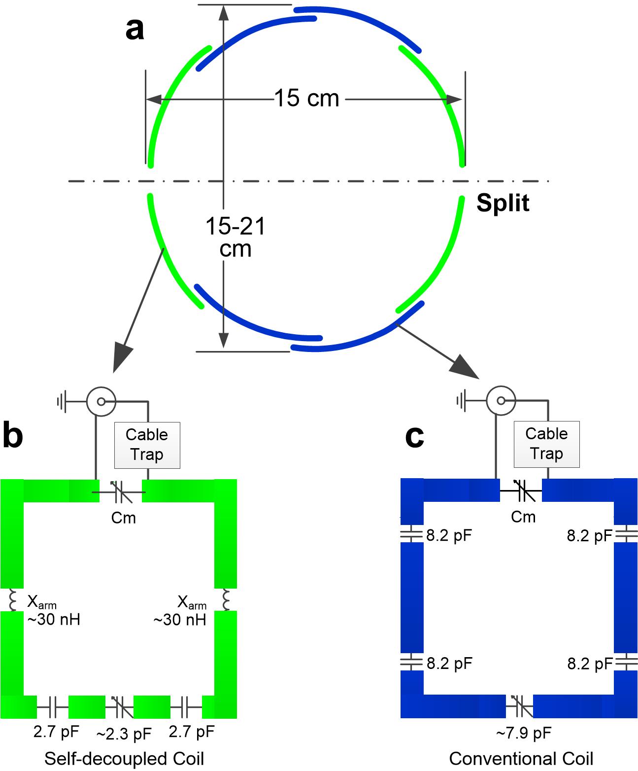
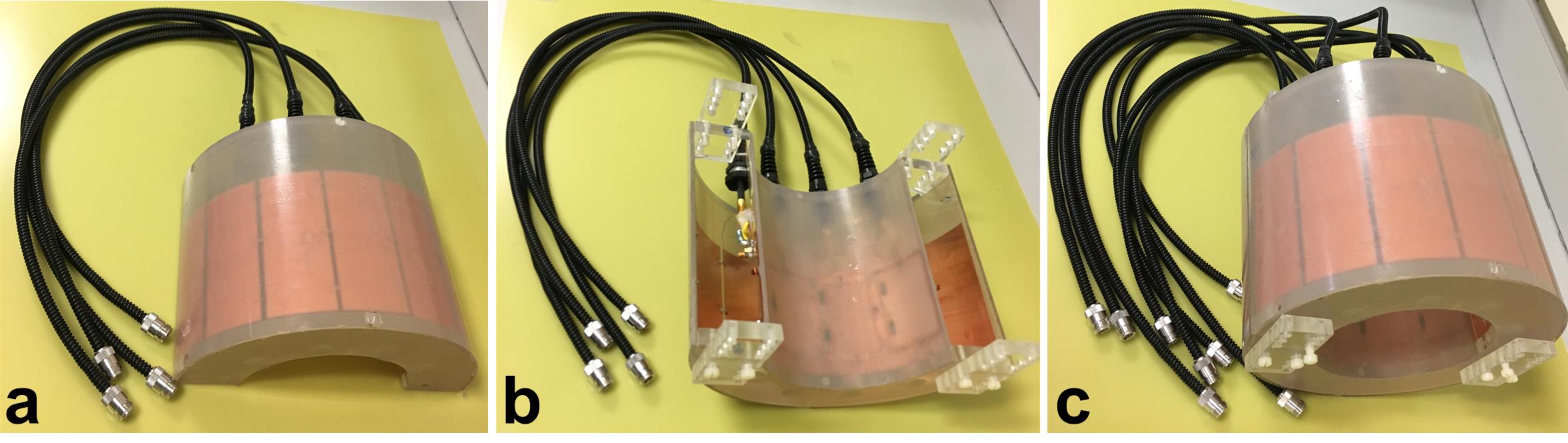
Fig.1a shows the cross-sectional geometry of the 8-channel transmit/receive array for 7T knee imaging. The array comprises 4 self-decoupled loop coils3 (green) and 4 conventional loop coils (blue). Figs. 1b and 1c show the schematics of a single self-decoupled coil and a single conventional coil, respectively. The array can be split between the self-decoupled coils (dotted line in Fig. 1a) because they are intrinsically decoupled. Their decoupling performance is robust for different coil-to-coil distances, so the two halves’ separation can be easily adjusted. The other adjacent elements are overlapped to minimize coupling. Fig. 2 shows the fabricated halves (Fig. 2a and Fig. 2b) and the two of them together (Fig. 2c). Each coil (6x7 cm2 dimension) was mounted on the outside of an acrylic tube (15 cm diameter and 20 cm length). An RF shield was mounted inside the outer coil housing 4.5 cm away from the coils to reduce RF radiation and cross-talk with other system components. Access is facilitated by removing the top half, allowing the leg to lie in the bottom half of the coil. Screws or belts can be used to attach the two halves together. Bench measurements were performed with an Agilent network analyzer. MR experiments were performed on a 7T whole-body scanner (Philips Healthcare, Best, Netherlands) with 8 transmit channels. Axial B1+ maps from the individual channels and all channels together (driven in CP mode) were acquired using the DREAM method4. We also compared the receive SNR with a commercial 28-cm-diameter volume coil (Nova Medical, Wilmington, MA). The receive SNR was calculated from low-flip-angle GRE images (TR/TE: 5000/10 ms, flip angle: 10°, slice thickness: 3.5 mm, in-plane resolution: 2x2 mm2, bandwidth: 962 Hz/pixel) using: image magnitude/std (noise)/normalized |B1+|.
Results
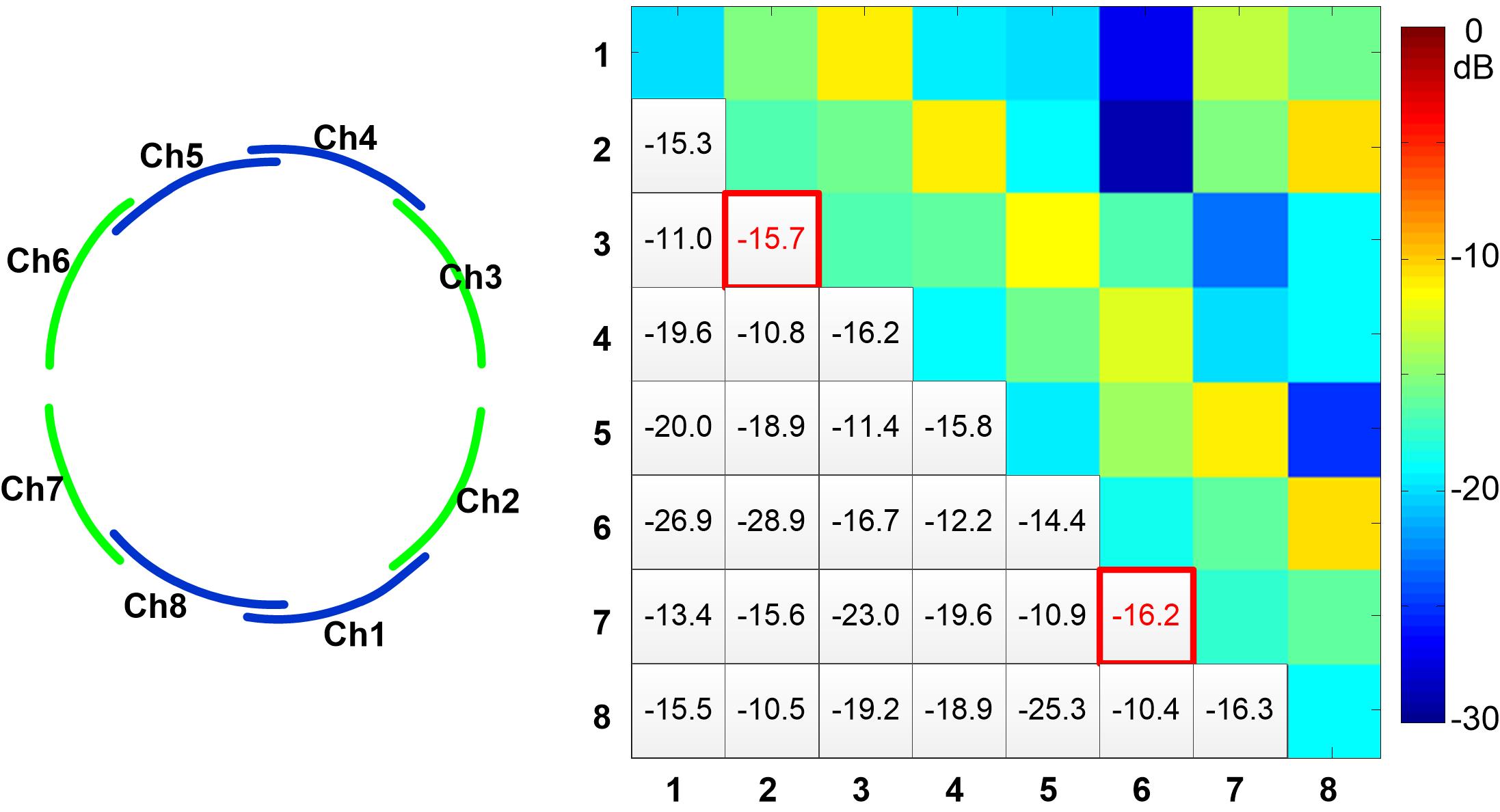
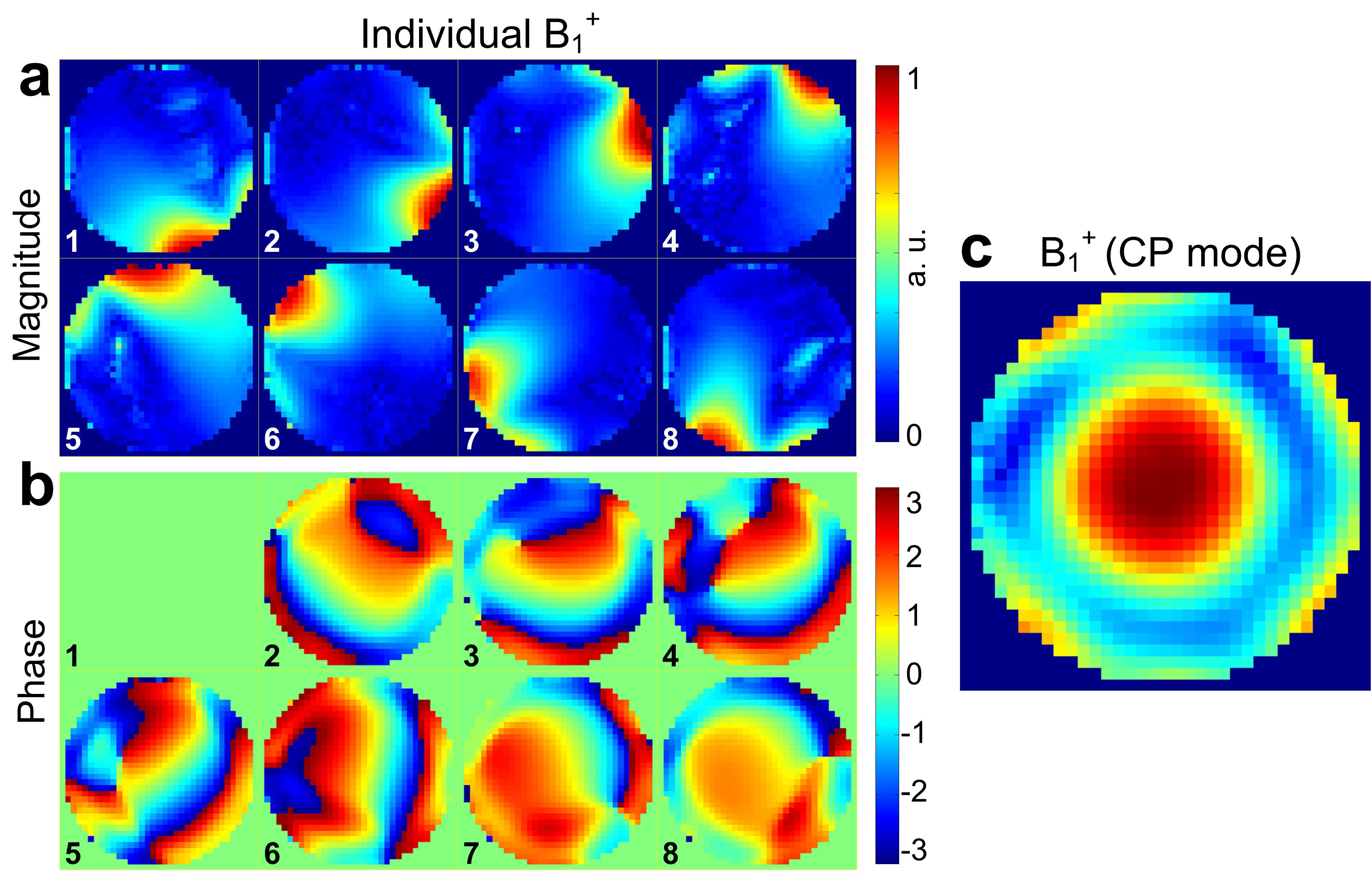
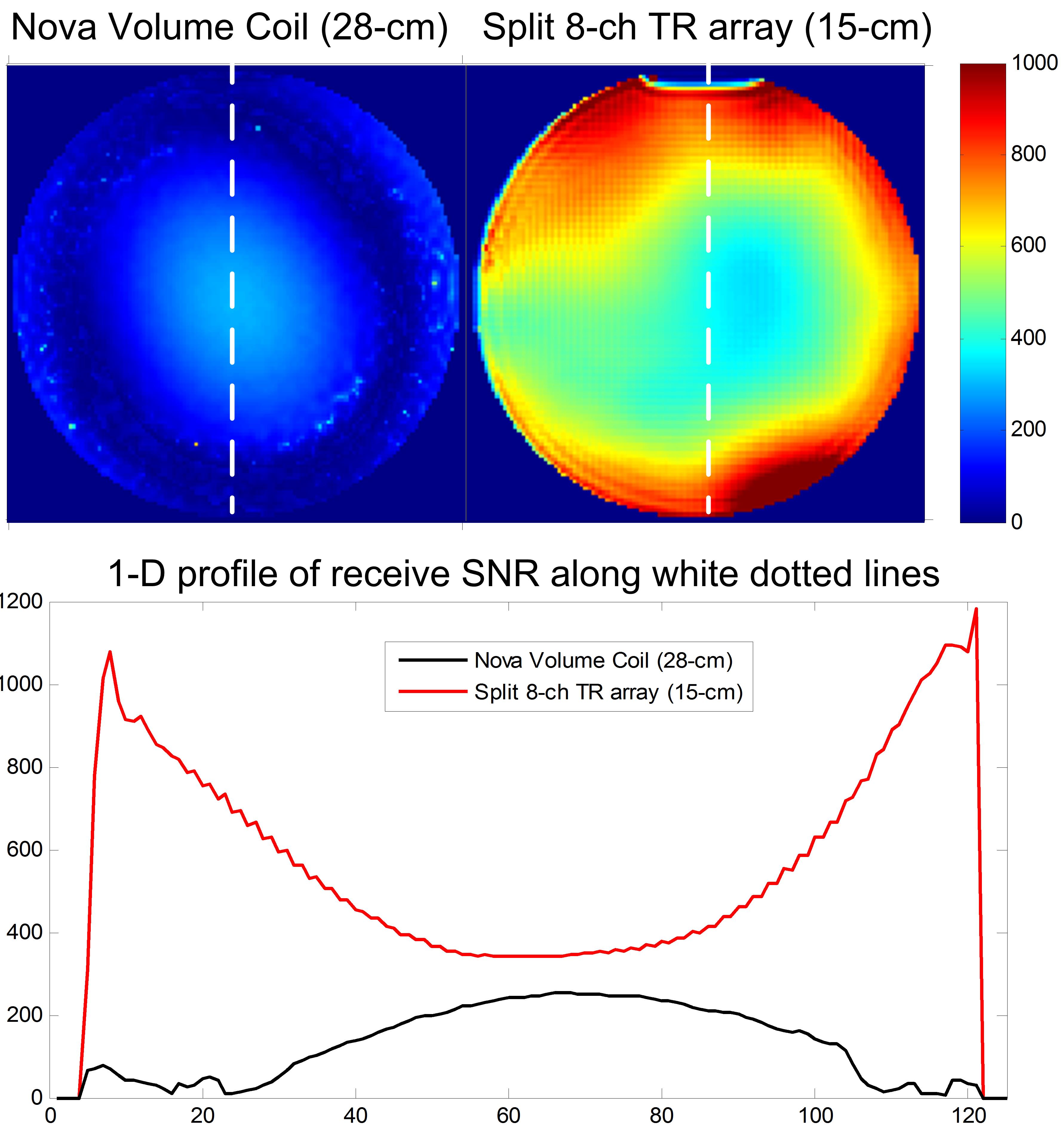
Fig. 3 shows the measured S-parameter matrix when the array was loaded with a 12-cm-diameter bottle phantom. The worst-case coupling is between next-adjacent loops (average -11.3 dB). The average coupling between adjacent elements (including the two adjacent self-decoupled coils), next-two adjacent and opposite elements are -15.7 dB, -20.2 dB and -22.7 dB, respectively. Figs. 4a and 4b show the magnitude and phase of B1+ maps of individual channels. It can be seen from Fig. 4a that the self-decoupled coils have similar B1+ patterns and efficiency as the conventional coils. Fig. 4c shows the B1+ map driven with all channels in CP mode (same amplitude, sequential 45-degree increments). Compared to the large commercial coil, the tight-fitting split coil has an SNR improvement of 30% at the central area and 8-fold in the peripheral areas (Fig. 5), respectively.Discussion and Conclusion
We described a novel split design for an 8-ch transmit/receive knee coil at 7T. The main benefits of this split coil compared to conventional designs are its simple structure and that it does not require physical connections between the halves, or impose geometric restrictions. This design could be extended to other applications such as head and body imaging to permit easy access. Future work will focus on safety tests and in-vivo experiments.Acknowledgements
This work is supported by NIH Grants R01 EB016695 and R21 EB 018521.References
1. De Zanche, Nicola, et al. "Asymmetric quadrature split birdcage coil for hyperpolarized 3He lung MRI at 1.5 T." Magnetic resonance in medicine 60.2 (2008): 431-438.
2. Keil, Boris, et al. "A 64‐channel 3T array coil for accelerated brain MRI." Magnetic resonance in medicine 70.1 (2013): 248-258.
3. Yan X, Gore J C, Grissom W A, Self-Decoupled RF Coils, ISMRM, (2017): 757.
4. Nehrke, K. & Bornert, P. DREAM--a novel approach for robust, ultrafast, multislice B(1) mapping. Magn Reson Med 68, 1517-26 (2012).
Figures