4271
Multi-row and Loopole-type Self-decoupled RF Coils1Institute of Imaging Science, Vanderbilt University, Nashville, TN, United States, 2Department of Radiology and Radiological Sciences, Vanderbilt University, Nashville, TN, United States, 3Department of Biomedical Engineering, Vanderbilt University, Nashville, TN, United States
Synopsis
Self-decoupled coils that do not require additional decoupling treatments provide increased freedom for RF array design. However, only a single-row array was demonstrated in the initial work and it is not clear whether this design can be applied to multi-row arrays. Furthermore, the initial self-decoupled coil was fed in a horizontal conductor and thus its B1 field was same as that of a conventional loop. If fed at a corner or in a vertical conductor, the self-decoupled coil may exhibit asymmetric currents and act as a “
Purpose
Self-decoupled coils1 that do not require additional decoupling treatments provide increased freedom for RF array design. However, only a single-row array was demonstrated in the initial work and it is not clear whether this design can be applied to multi-row arrays to provide greater volume coverage and RF encoding capability2-4. Furthermore, the initial self-decoupled coil was fed in a horizontal conductor (leading to symmetric currents in its vertical conductors) and thus its B1 field was same as that of a conventional loop. If fed at a corner or in a vertical conductor, the self-decoupled coil may exhibit asymmetric currents and act as a “loopole” which can be used to improve B1/√SAR efficiency5. In this work, we proposed several solutions for multi-row arrays and also investigate loopole-type self-decoupled coils.Methods
Multi-row Self-decoupled Coils
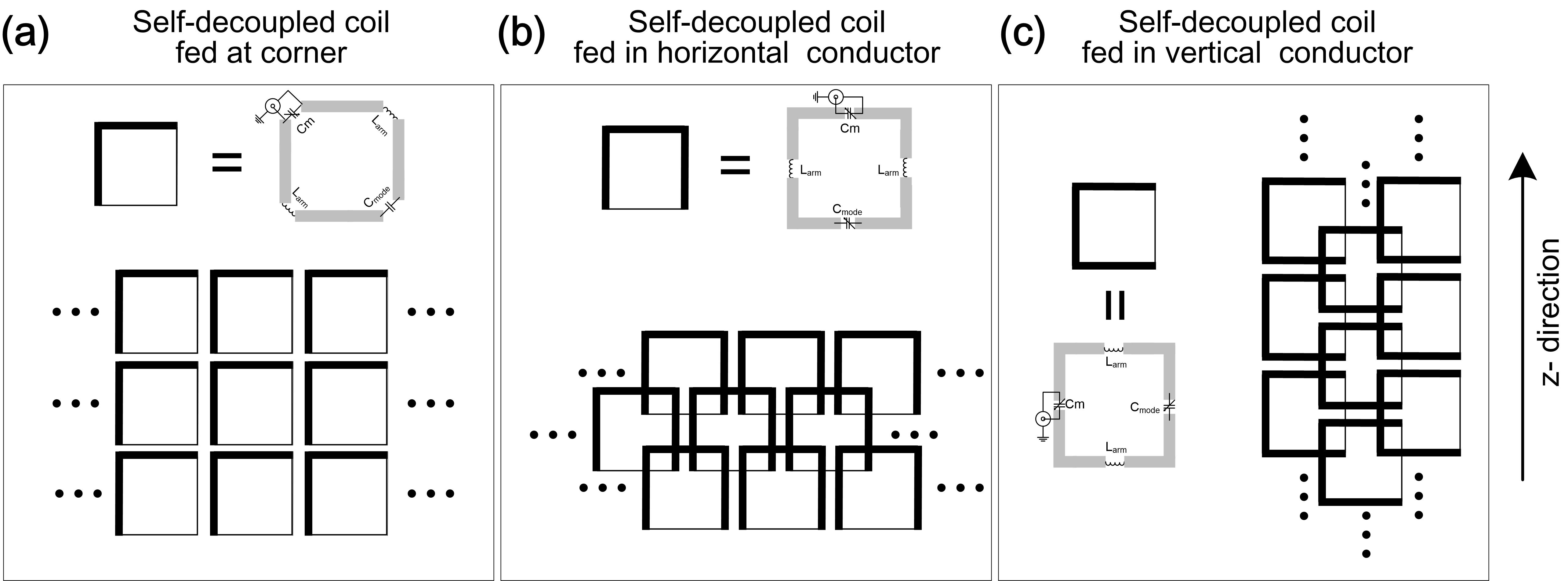
Fig. 1 illustrates different kinds of coil arrangements for multi-row self-decoupled coils, which are referred to as corner-fed (Fig. 1a), horizontal-fed (Fig. 1b) and vertical-fed (Fig. 1c). In the corner-fed arrangement (Fig. 1a) dipole modes are generated in both the horizontal and vertical directions, which is expected to decouple adjacent elements in the same row and decouple adjacent elements in different rows simultaneously. So this design may not require additional decoupling treatments. In the horizontal- and vertical-fed arrangements (Fig. 1b), the self-decoupled coil only generates the desired dipole-mode along the one direction. Therefore another decoupling treatment is needed to decouple elements in the other direction (overlapping was used here). Note that corner- and vertical-fed arrangements exhibit asymmetric currents in the vertical conductors that lead to loopole-type B1 patterns5 (discussed later). To validate these designs, different 2x2 self-decoupled arrays were simulated for 7T (298 MHz) MRI. The corner fed array was built and tested. We also investigated the coupling performance of 24-ch and 32-ch multi-row arrays for different applications through simulation.
Analysis of Loopole-type B1 field
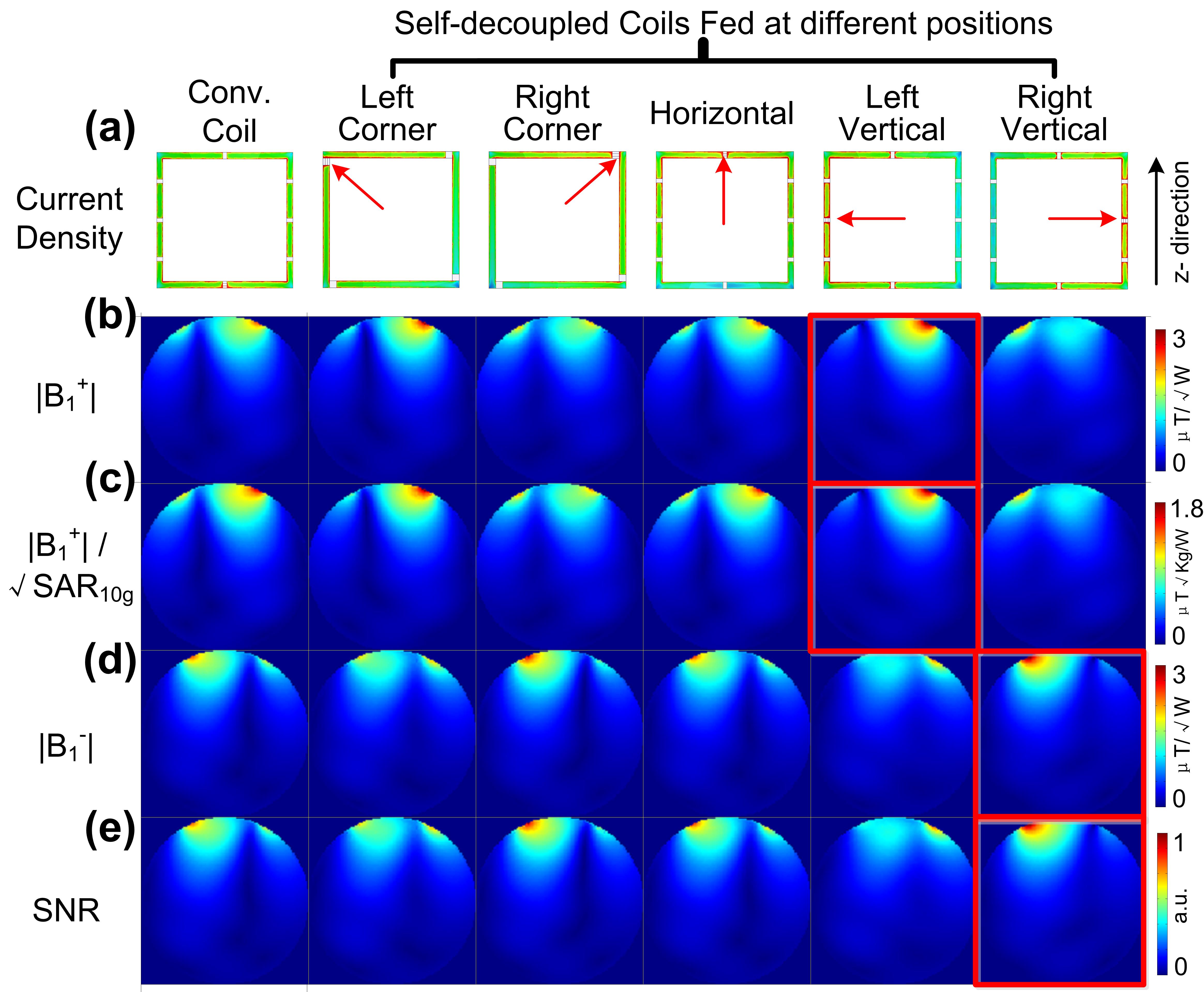
The B1=(Bx±iBy)/2 is mainly determined by currents along the vertical conductors. For horizontal-fed self-decoupled coils, the current along the vertical conductors are symmetric and exhibits the same B1 field (both pattern and efficiency) as the conventional loop coil. However, the current along the vertical conductors becomes asymmetric when the coil is corner- or vertical-fed, stronger near the feed port and weaker near the Cmode. This asymmetric current should lead to a loopole-type B1 pattern. To validate this, B1 fields of self-decoupled coils fed at different positions (corresponding to the corner-fed, horizontal-fed and vertical-fed multi-row arrangement) were comparatively investigated through simulation. The EM simulations were performed with HFSS software (Ansys, Canonsburg, PA, USA).
Results
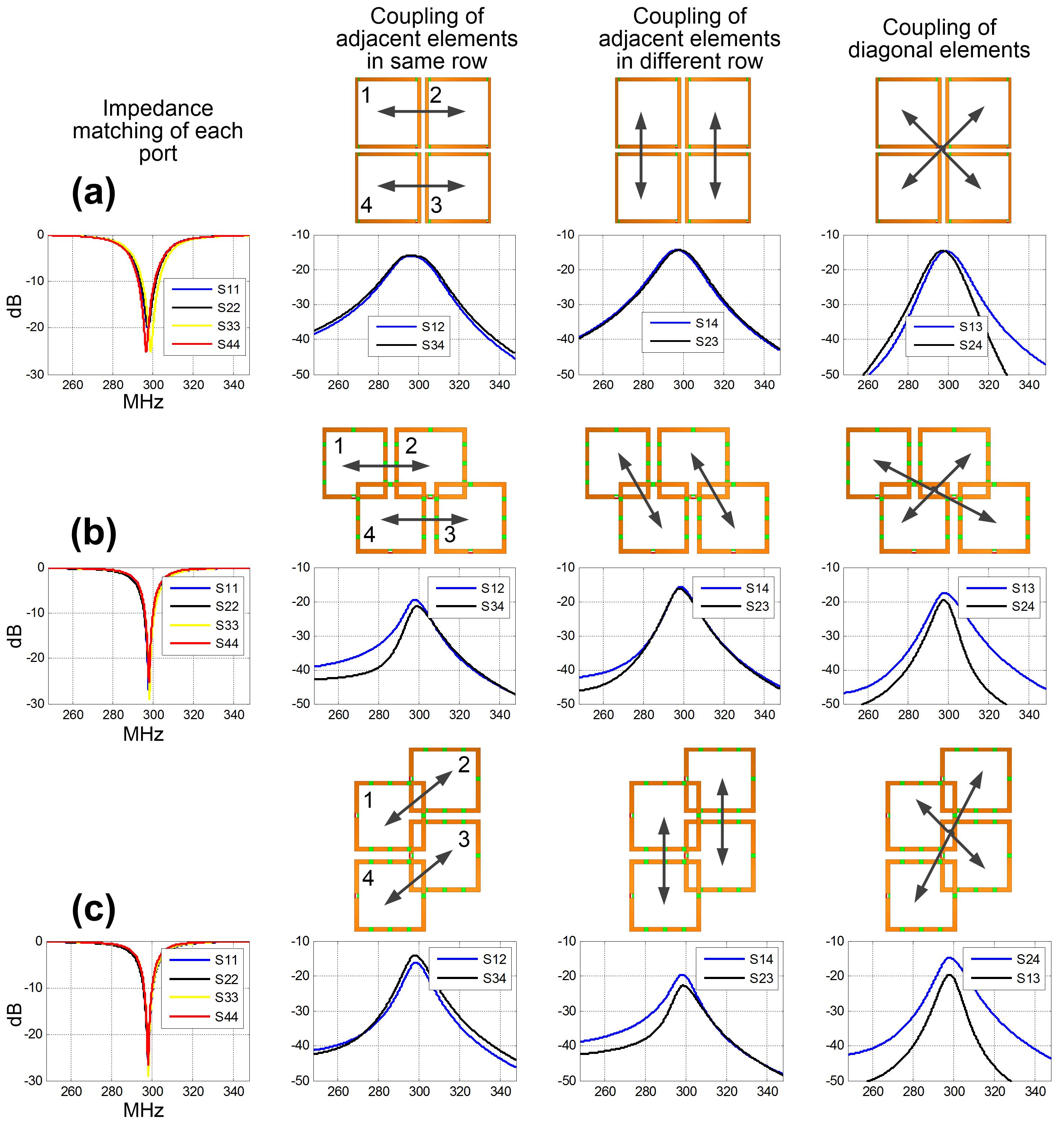
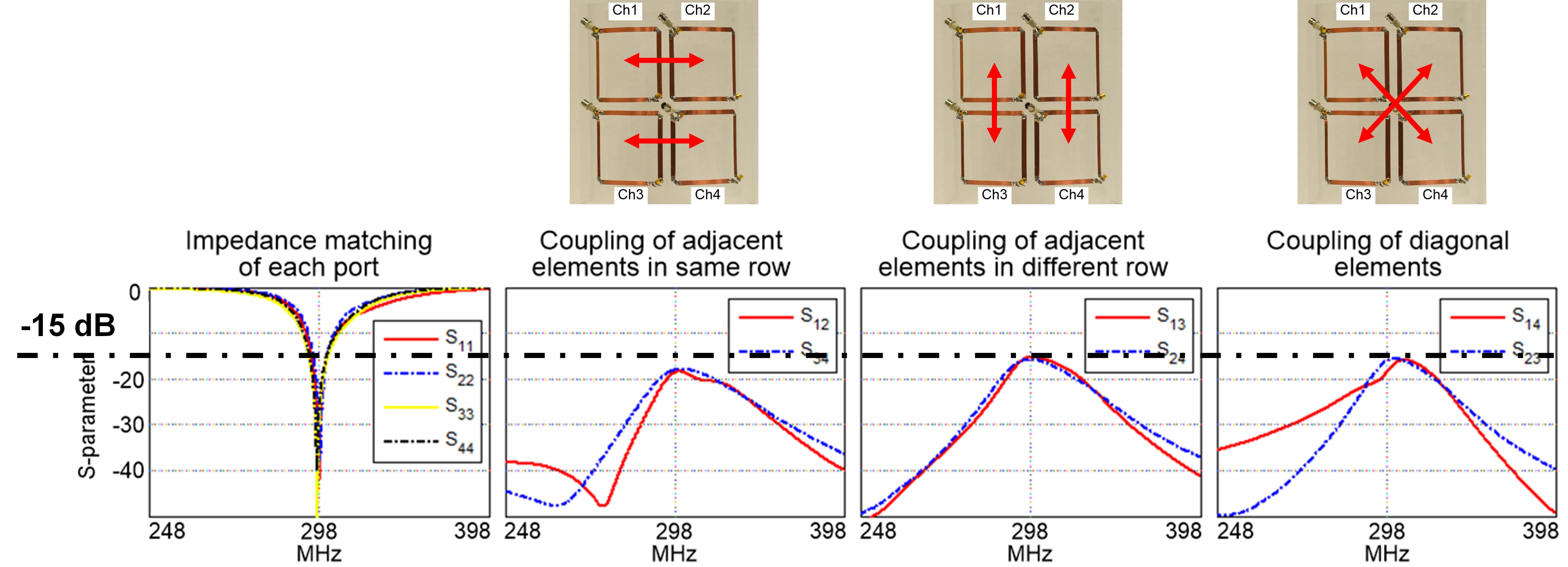
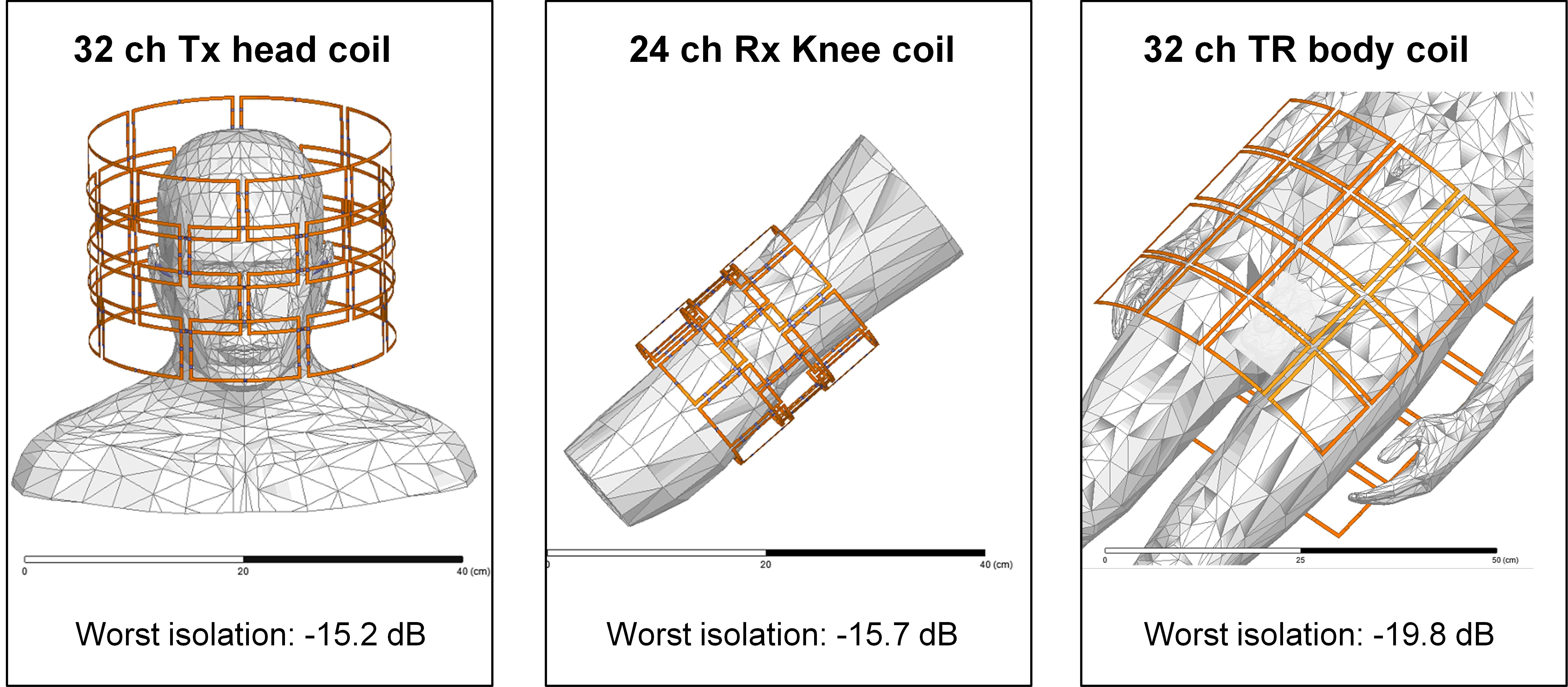
Fig. 2 shows the simulated S-parameter plots of three 2x2 self-decoupled arrays using different arrangements. These arrays (each coil 10x10 cm2) were mounted on 25-cm-diameter cylindrical former. A 16 cm-diameter cylinder phantom was placed 4.5 cm below as a load (б=0.6 S/m and ξr=78). For all these arrays, the worst-case isolation was approximately -14 dB. The corner-fed 2x2 array was also validated in bench tests (Fig. 3). Fig. 4 shows simulation models of a 32-ch head array, a 24-ch knee array and a 32-ch body array using the multi-row self-decoupled design. For all these arrays, the worst-case inter-element isolation was still better than -15 dB (marked at the bottom of Fig. 4).
Fig. 5 shows simulation results of a conventional coil (uniform current distribution) and different self-decoupled coils (fed at different positions). These coils have a dimension of 10x10 cm2 and placed 1 cm below a 20-cm-diameter phantom (б=0.6 S/m and ξr=78). By feeding in the vertical conductor, the self-decoupled coil did exhibit "loopole-type" B1 patterns, which can increase either B1+ or B1- (red box in Fig. 5) at the expense of decreasing the other. This lead to notable improvement in transmit efficiency and SNR (around 20%), but little improvement in the safety efficiency (B1+/√MaxSAR10g). This is mainly because the self-decoupled coil increased MaxSAR10g by 25% in this specific case.
Discussions and Conclusion
With a simple modification (fed at corner) or adding another decoupling method (such as overlapping), the self-decoupled coil design can be applied to multi-row arrays. The self-decoupled method could also be used to improve transmit efficiency and SNR by optimizing the feed port’s positions. In this specific case (cylindrical phantom), we did not find notable improvement in B1+/√MaxSAR10g.Acknowledgements
This work was supported by NIH R01 EB 016695 and NIH R21 EB 018521.References
1. Yan X, Gore J C, Grissom W A, Self-Decoupled RF Coils, ISMRM, p. 757 (2017).
2. Poser, Benedikt A., Robert James Anderson, Bastien Guérin, Kawin Setsompop, Weiran Deng, Azma Mareyam, Peter Serano, Lawrence L. Wald, and V. Andrew Stenger. "Simultaneous multislice excitation by parallel transmission." Magnetic resonance in medicine 71, no. 4 (2014): 1416-1427.
3. Wu, Xiaoping, Jinfeng Tian, Sebastian Schmitter, J. Tommy Vaughan, Kâmil Uğurbil, and Van de Moortele. "Distributing coil elements in three dimensions enhances parallel transmission multiband RF performance: A simulation study in the human brain at 7 Tesla." Magnetic resonance in medicine 75, no. 6 (2016): 2464-2472.
4. Shajan, Gunamony, Mikhail Kozlov, Jens Hoffmann, Robert Turner, Klaus Scheffler, and Rolf Pohmann. A 16‐channel dual‐row transmit array in combination with a 31‐element receive array for human brain imaging at 9.4 T." Magnetic resonance in medicine 71, no. 2 (2014): 870-879.
5. Lakshmanan K, Cloos M, Lattanzi R, Sodickson D K, and Wiggins G, The Loopole Antenna: Capturing Magnetic and Electric Dipole Fields with a Single Structure to Improve Transmit and Receive Performance, ISMRM, p. 397(2014).
Figures